
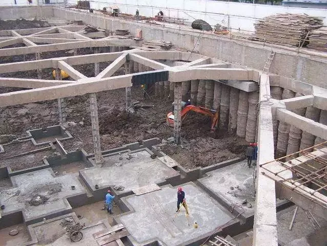
As building scales continue to expand, the reverse construction method has become increasingly popular in construction projects. Below, we summarize the key technical points essential to this method. Let’s explore them together.
Diaphragm Wall
1. Guide Wall Construction
When constructing guide walls, it’s important to consider the characteristics of the topsoil, groundwater conditions, and load factors. Typically, the guide wall depth ranges from 1 to 2 meters, with the top approximately 1 meter above ground level, and a thickness between 15 and 20 cm.
The basement’s outer wall is usually an underground continuous wall designed to resist horizontal forces from soil and water pressure, making it a critical component in reverse construction. Guide walls are generally made of cast-in-place reinforced concrete and are reusable.
During construction, ensure the wall’s toe exceeds 20 cm and that the top surface remains horizontal. The base should be tightly aligned with the soil surface, and the inner wall should be parallel to the axis of the underground continuous wall to prevent mud infiltration into the trench.
Typical construction steps include site leveling, trench measurement, soil treatment, formwork installation and removal, outer wall construction, and soil backfilling. After completion, two wooden blocks are placed at the top and bottom to support the guide wall and prevent deformation caused by pressure or other forces.
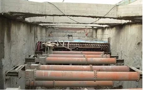
2. Deep Trench Excavation
Excavation is a crucial phase in building underground continuous walls. Generally, it accounts for half of the construction period for these walls, so precise timing and accuracy are essential, especially in prefabricated assembly projects.
Soil layer stability must be carefully monitored; unstable layers may require shorter trench sections. Concrete pouring should follow excavation promptly to reduce construction time and minimize collapse risks. In areas near tall buildings or complex conditions, keep trench lengths and exposure durations minimal to maintain wall stability.
Underground continuous wall joints can be either rigid or flexible, with the choice depending on specific project requirements.
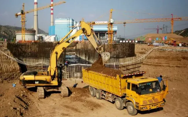
Earth Excavation
If settlement differences between adjacent columns exceed alarm thresholds during construction, upper structure work should be halted, and excavation speed increased. Conversely, in some sections, excavation may need to slow down or be reinforced and grouted as required.
Effective control of excavation length, depth, and width is vital, with accurate calculations of impact coefficients and ranges. Time effects must also be considered.
When selecting soil outlet locations, ensure natural ventilation during underground excavation and structural stress requirements are met. Excavators perform secondary soil excavation at a horizontal distance to maintain efficiency, allowing a single outlet to serve three strip extraction areas during bottom plate excavation.
Earth excavation methods include open excavation, hidden excavation, and cover excavation. Reverse construction commonly employs underground excavation, following principles of balance, symmetry, phased division, layering, and time limits. Excavation proceeds via balanced block division and symmetrical strip drawing.
Settlement Difference Management
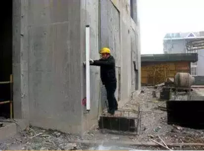
Managing settlement differences is critical when applying the reverse construction method. Underground continuous walls are installed in a ring around the site. Excavation stress release combined with upper loads can cause both uplift and settlement in these walls. Excessive settlement can compromise structural safety. Generally, settlement differences should remain below 20 mm.
If the threshold is exceeded, construction on the upper structure must pause, and local reinforcement should be applied. Excavation speeds may be adjusted accordingly—either slowed or accelerated in specific areas.
To address column pile uplift during foundation pit excavation, frictional resistance reduction on the upper pile section is an effective method. Reinforcement through added support or pre-loading can also mitigate uplift-related settlement.
Enhancing column pile bearing capacity—by increasing pile diameter, grouting pile bottoms, or selecting high-capacity pile ends—helps reduce settlement differences. To prevent uneven deformation caused by column rigidity, integrated decorative knife supports can be used to temporarily and permanently strengthen walls.
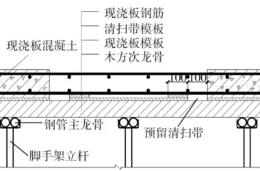
Floor Formwork Support
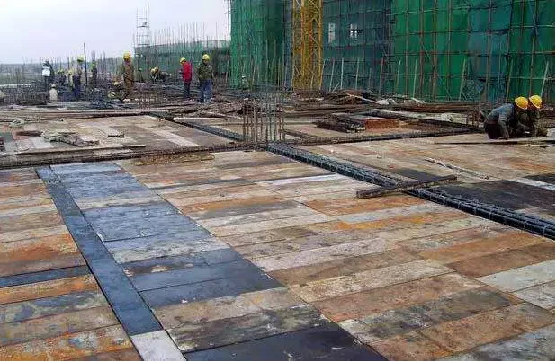
1. Soil Mold Load-Bearing Capacity
Before constructing soil formwork, excavate the soil to the design elevation, then level and compact it. Following this, pour a 50 cm thick plain concrete cushion layer. Once this concrete has partially set and hardened, apply cement mortar leveling based on the beam formwork support points, keeping elevation deviations within specified limits.
2. Formwork Construction and Support
Excavate a soil layer within the underground structure, then set up beam and slab formwork using standard methods. After reinforcing the beam and slab structure, proceed with concrete pouring, followed by vertical structural construction extending from bottom to top.
Foundation Pit Support
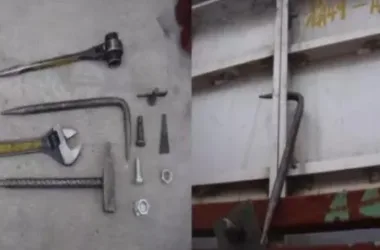
1. Soil Nail and Composite Soil Nail Wall Technology
This involves using slender rods that, when the foundation pit soil experiences external forces or changes, transfer forces between the soil and nails to protect the pit.
2. Pile Support Technology
This technique employs supporting structures such as anchor rods, cast-in-place concrete piles, and steel piles combined with internal soil supports. The construction process involves bored pile installation, pile driver relocation, post-grouting maintenance, and broken pile crown beam construction. Pile driving methods include separate and surrounding purlin driving.
3. Surrounding Slope Excavation Technology
This refers to earthwork excavation and slope formation around the foundation pit, following the designed slope angle.
Node Construction
01. The “Two Walls in One” Method
The “two walls in one” approach uses retaining walls as structural or partial structural walls, optimizing their function to reduce costs and promote green construction.
In integrated designs, a stacked lining wall approximately 300 mm thick is placed inside the underground continuous wall to block groundwater.
In separated designs, wall columns are positioned at the joints of the underground continuous wall, with brick or concrete isolation lining walls between them. Waterproofing uses a “diversion” method, with a drainage ditch between the underground continuous wall and lining wall to channel any leaked water.
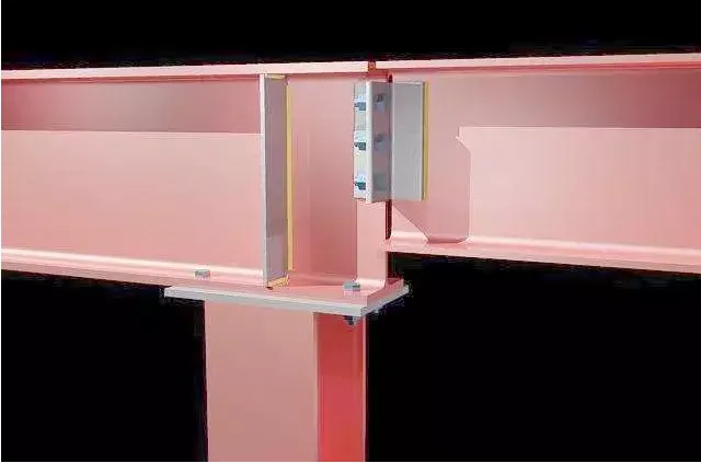
02. Connection Between Underground Continuous Wall and Floor Slab
Since temporary enclosure wall support is replaced by floor slabs, a reliable support system is crucial to transmit horizontal forces from the enclosure wall to the floor slab. This is typically achieved through force-transmitting steel.
Key considerations include:
- When permanent columns are not yet formed, floor beams or slabs rest on lattice columns. Vertical force transmission at nodes requires installation of shear-resistant steel bars, bolts, or steel supports on these columns.
- Grid column steel plates can obstruct longitudinal reinforcement penetration in beams; adding horizontal armpits at beam nodes helps resolve this.
03. Steel Tube Concrete Column and Beam-Slab Joint
Similar to lattice columns, solutions include circular steel supports, bolts, and reinforced concrete ring beam joints to address joint issues.
04. Node Between Steel Column and Column Pile
The ideal approach is a single pile cap supporting one column (“one column, one pile”), which offers a simple structure, easy construction, and good cost efficiency.
When designing with multiple piles per column, pile arrangements should ensure piles are located under columns to support steel columns effectively. Column pile bearing capacity during construction must be verified.
If no piles lie beneath columns, multiple steel columns and support beams atop the columns are needed to transfer loads, increasing resource use and construction complexity, so this should be avoided when possible.
05. Horizontal Force Transmission in Special Areas
(1) For post-pouring sections of the structure, pre-embedded steel with bolts on both sides inside the concrete is used. Concrete transfer plates can also be added beneath the bottom plate.
(2) For staggered horizontal structures, an auxiliary inclination not exceeding 1/2 is applied.
Article source: Architectural Technology Magazine


Must log in before commenting!
Sign Up