The construction quality of prefabricated buildings is a crucial factor in ensuring overall engineering excellence. Achieving prefabricated buildings that meet seismic standards, quality benchmarks, and aesthetic requirements relies heavily on rigorous construction management.
To deliver high-quality prefabricated buildings, strict control must be maintained over both design and construction quality. Particular attention should be given to the following essential “6+1” stages, which are critical for success.
One / 6. Deepening Design
01 Understand Deepening Design Requirements
(1) Detailed drawings for prefabricated components production must be based on the reserved and embedded requirements across all specialties, production, and construction. Any conflicts discovered in these drawings should be promptly flagged for timely modifications to the prefabricated component design.
(2) Verify the detailed drawings to ensure they meet regulatory and installation requirements. The construction team should be familiar with national standards and specifications related to prefabricated components, and confirm that the depth and content of the drawings fulfill production, quantity estimation, and installation needs during the deepening design phase.
02 Complete Detailed Design Content
(1) Construction methods for exterior wall decoration and finishes should be clearly defined. Deepening design should focus on layout details for tiles, decorative concrete, stone, etc., ensuring material types and quantities align with design specifications. Additionally, stone procurement must meet aggregate strength and aesthetic standards.
(2) Energy-saving and insulation structures for exterior walls must fulfill building functional requirements. Careful selection of insulation materials and connectors is essential, along with precise layout details. Design performance should be verified, and prefabricated R&D must complete the design calculation verification process.
Focus on the Production Process of Prefabricated Components
(1) Production Plan: The construction team should actively participate in designing and adjusting the production plan according to drawing requirements to ensure smooth and consistent component manufacturing.
(2) Mold Scheme: The construction party must confirm that the design drawings meet construction needs, collaborating to detect any issues in mold production and provide prompt modification suggestions.
(3) Personnel Organization: Assign dedicated personnel to oversee component production quality, verifying strength, dimensions, and appearance. A liaison should communicate regularly with the component factory, providing timely updates and relaying construction requirements.
(4) Technical Quality Control: The quality of components significantly affects subsequent assembly and installation. Emphasize timely communication with manufacturers, conduct strength tests, and request rework if components fail to meet installation standards or deviate significantly in size.
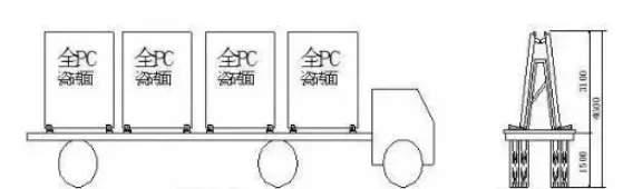
(5) Storage and Transportation Plan: Ready-to-use components and minimizing transportation distances are key to conserving space during prefabricated installation.
Two / 6. Organizational Planning and On-site Layout
01 Organizational Planning
Once the project scope is clarified, a detailed construction organization design should be developed. This document should highlight the unique aspects of prefabricated structural installation, demonstrate construction organization and deployment scientifically, justify construction processes, and confirm the technical and economic feasibility of chosen methods. It should effectively guide on-site work by organizing resources such as personnel, machinery, materials, and tools to complete prefabricated installation, and propose solutions to technical challenges.
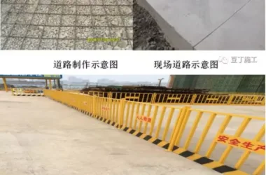
02 Construction Site Layout Plan
(1) Component Storage Yard: The yard must accommodate assembly requirements for each construction flow section and allow for the safe passage and loading/unloading of large transport vehicles and cranes. To ensure site safety, the component yard should be enclosed to restrict unauthorized access.
(2) Loading and Unloading Points: Prefabricated components are transported by large vehicles, often in large quantities with lengthy loading and unloading times. Therefore, these points should be strategically placed to avoid traffic congestion and interference with other on-site operations. Ideally, loading/unloading zones should fall within the reach of tower cranes or lifting equipment and never be located on main roads.
Three / 6. Vertical Lifting
01 Vertical Lifting Equipment and Tools
(1) Tower Cranes: Currently, tower cranes fall into fixed, attached, or internal climbing types based on installation, and are categorized by slewing forms into small car slewing and boom slewing.
(2) Crane Selection: For prefabricated structures, tower cranes must have a lifting height that equals the building height plus safe lifting height, the maximum height of prefabricated components, and rigging height.
(3) Crane Coverage: The tower crane model determines boom length and amplitude. When positioning cranes, ensure the boom covers the component yard fully to avoid blind spots and minimize secondary handling.
02 Lifting Sequence
The typical lifting sequence for prefabricated components is as follows: prefabricated walls → composite beams → composite panels → staircases → balconies → air conditioning panels.
For external wall hoisting, start with corner walls, using them as positioning references for other wall elements. The PCF board is installed after the adjacent prefabricated external walls have been hoisted and aligned.
Four / 6. Construction Details
01 Installation of Prefabricated Composite Panels
(1) Use modular lifting beams during the hoisting of composite panels, proceeding slowly to maintain stability.
(2) Pause briefly about 300 mm above the working layer to adjust and align the panel direction. Avoid collisions, and place panels steadily to preserve integrity.
(3) Install temporary supports under the panels spaced approximately 150 cm apart, with 2-3 rows of supports per bay.
(4) For structural layer construction, double-layer supports are required. Supports can only be removed once the cast-in-place concrete achieves at least 70% of its design strength.
02 Prefabricated Stair Board Installation
(1) When hoisting stair treads, pause roughly 500 mm above the work surface, adjust orientation carefully, and lower slowly to prevent damage from shaking or folding.
(2) Once roughly positioned, use pry bars for fine adjustments along control lines, then weld and secure.
03 Key Points for Prefabricated Beam and Slab Construction
(1) Prepare pedestals as required, ensuring anti-arch settings are correct.
(2) Conduct concrete pouring with proper vibration compaction and apply isolation agents to formwork.
(3) Pre-stressing and tensioning should occur after wet curing, once concrete strength reaches 80%.
(4) Perform tensioning symmetrically, verifying stress through controlled elongation values.
(5) Follow the tensioning sequence: 0 → initial stress → over-tension by 5% holding load for 2 minutes → anchoring.
(6) Apply timely grouting, typically using cement slurry or mortar, with pressure between 0.5-0.7 MPa.
04 Installation of Prefabricated Bay Windows
(1) Bay windows are lifted using lifting ears, bolts, and reserved nuts.
(2) After connection, carefully move the bay window to about 300 mm from the work surface according to position lines. Align the bay window bolts with wall panel holes, place the custom U-shaped horizontal interlock measure set, and use a sliding rope to guide bolts into the connection holes.
Five / 6. Seismic Construction
Seismic performance is a critical safety and quality concern for prefabricated buildings, requiring collaboration between design and construction teams.
Shock-absorbing columns are designed to absorb all earthquake energy, protecting key columns and beams from damage. These columns feature symmetrical steel plates with flanges connected reliably to prefabricated structural beams, with softer steel (low yield point) in the middle.
Placement involves positioning shock absorber columns on the left and right spans of three-span PC columns inside the inner cylinder, two on each side, and eight per floor. The inner cylinder frame experiences significant horizontal forces, especially at corners, so placing shock absorbers there maximizes energy absorption and structure protection. Only 3/4 of the column height is fitted with absorbers, as the bottom bears the main horizontal shear and overturning moments. While top displacement is higher, it remains within safe limits due to shock absorbers operating at lower levels. For high-rise bending shear structures, maximum horizontal shear typically occurs mid-floor; inserting low yield point steel in these areas aids in shear force bearing and energy dissipation.
During construction, besides seismic design, node connections must be carefully managed to ensure overall seismic integrity.
Structural connections include equivalent cast-in-place and prefabricated connections. Equivalent cast-in-place connections should meet or exceed the seismic performance of traditional cast-in-place concrete joints, commonly using post-cast integral or prestressed splicing joints. Prefabricated connections differ mechanically and often utilize welded or bolted nodes.
Six / 6. Preventive Measures
01 Use of Auxiliary Tools
(1) L-shaped lifting devices are recommended for corner panels to prevent breakage during transport and lifting by transferring tensile forces to the lifting equipment, reducing damage rates.
(2) Flat panels are susceptible to corner damage during transport. Custom plastic or rubber corner protectors should be made according to component thickness and size.
(3) Employ the method of “increasing spacing and frequent small batch transport” during flat panel transportation. Increasing distance between panels and using smooth transport routes with more frequent trips helps prevent breakage.
02 Reduce Composite Panel Span
To avoid fractures caused by excessive span during lifting, coordinate with design teams to limit composite panel spans within allowable deflection ranges during the design stage, minimizing damage risks during on-site handling.
03 Hoisting Truss Reinforcement
Pre-embedded parts may detach during composite panel lifting. Reinforcing around these parts or lifting via truss bars directly is advisable. This approach reduces lifting costs, ensures safety, and allows flexible adjustment of lifting points based on site conditions.
04 Increase Alignment Apertures
Alignment between prefabricated steel bars and on-site reinforcement holes is a persistent challenge. Increasing steel bar alignment holes within regulatory limits improves penetration rates and longitudinal steel continuity, enhancing effective connections. Enhanced communication between on-site teams and component manufacturers can improve production accuracy and standardize steel reinforcement binding, reducing errors.
05 Secure Pre-embedded Components Before Vibration
Misalignment of junction boxes often occurs during concrete vibration of wall panels. Welding junction boxes before vibration effectively fixes their position. For embedded water and electrical pipelines, implement an inspection process before, during, and after vibration to significantly reduce detachment and improve finished product quality.
+1 “Full Process Acceptance”
Despite advances in prefabricated structure connections, quality risks remain at component joints. Superior construction methods can make post-construction inspection of connection quality difficult, and construction personnel’s expertise and techniques require ongoing improvement.
01 Acceptance of Prefabricated Components
(1) Verify that delivered component quantities match supply orders.
(2) Confirm that surface markings are complete, including production dates, certification status, and strength requirements.
(3) Inspect for defects such as honeycombs, rough surfaces, or cracks.
(4) Check if dimensional deviations are within allowable limits.
(5) Verify that reserved steel bar deviations meet requirements.
(6) Confirm processing, installation, and fixation deviations of embedded parts comply with standards.
(7) Ensure pre-embedded pipeline positions meet design tolerances.
(8) Review completeness of quality certification documents and process data.
02 On-site Construction Acceptance
(1) Accept sub-projects and sub-items: after successful quality acceptance of prefabricated structural works, file and record all documents under the concrete structure sub-project.
(2) Classify inspection batches for concrete structures: raw materials for prefabricated components, installation engineering, and grouting engineering should each be inspected by flow section as individual batches.
Editor in Chief: Pino


Must log in before commenting!
Sign Up