1. Preparation Inside and Outside the Site
1. On-Site Preparation
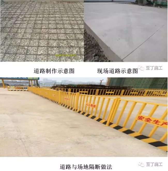
Prepare the construction site by ensuring the “three connections and one leveling” for roads, water, electricity, and the entire site. Set up temporary facilities and storage yards for precast concrete (PC) structures on site. To meet construction requirements for PC structure installation and handle the maximum weight of individual PC components, ensure the lifting distances for each building are achievable. According to the construction schedule and site layout, four STC7015 tower cranes are strategically placed near buildings 1 through 4 to guarantee the average lifting of nodes on each floor every 5 to 6 days.
2. Off-Site Preparation
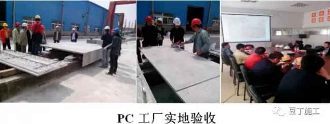
Maintain constant communication with PC manufacturers and related component suppliers outside the site. Accurately identify each manufacturer’s location and estimate the actual distance to the project site to coordinate delivery schedules effectively, optimizing overall construction planning. Conduct on-site assessments of manufacturers’ production capabilities and the types of PC structures they produce to develop realistic construction and entry plans based on these evaluations. Invite manufacturers to the construction site to review transportation routes and assess road conditions, including width, thickness, and corners. Before construction begins, quality inspectors from our company and supervising authorities will perform quality acceptance checks at the manufacturing facilities. Components failing to meet standards will be rejected; defective parts will be rectified or repaired at the factory before delivery.
2. Prefabricated PC Concrete Construction
1. Selection of Components and Production Scope
PC prefabricated components are manufactured in factories by specialized production units, then transported to the construction site where the general contractor handles hoisting and installation. Components include prefabricated exterior wall panels, stairs, balcony panels, protruding window panels, and equipment platforms, categorized based on their form and quantity.
2. PC Structure Transportation, Yard Setup, and Finished Product Protection
Transportation
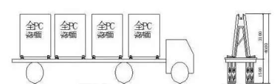
Vertical transportation of PC structures is preferred to minimize damage and simplify construction. Before loading, install lifting frames to securely hold the PC components with soft isolation materials, preventing damage during transit. To facilitate smooth entry and movement on site, a main access road at least 8 meters wide and a construction road at least 5 meters wide are established, allowing bi-directional vehicle passage and adequate turning space for transport vehicles.
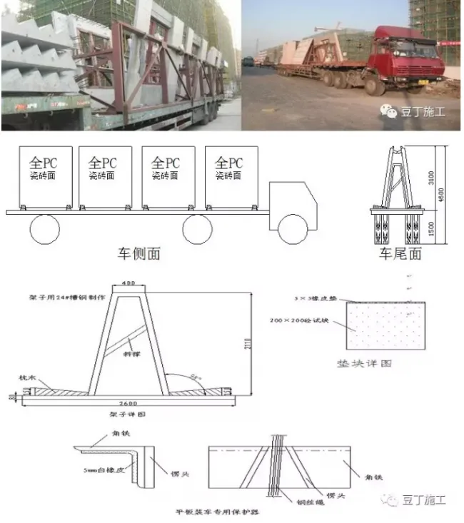
PC balconies, air conditioning panels, stairs, and equipment platforms are transported flat, with full-length wooden strips underneath and secured with strong ropes. Balconies and air conditioning panels can be stacked up to six pieces without exceeding height limits, while balcony and stair panels should not exceed three stacked pieces. Vehicles should accelerate slowly and maintain steady speed, especially when turning or changing lanes, to prevent overturning of wall panels.
Some transport routes pass over underground garages. To support the static load of PC transport vehicles, beams are reinforced with 16# I-beams to ensure structural safety during passage.
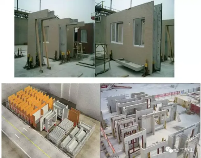
Yard Setup
This project’s PC components are characterized by heavy weight and limited length (up to approximately 4 meters and 4.6 tons each). To accommodate these requirements and facilitate hoisting, one PC yard is set up per building, located on the basement roof and reinforced appropriately. Surrounding construction roads are paved with 200mm thick C20 concrete, reinforced with single-layer bidirectional steel bars (Φ 18@150). Steel transport vehicles use the underground warehouse’s top slab as a construction road and material yard, with necessary reinforcements to support heavy loads. Bent steel pipes used for reinforcement will be removed after capping.
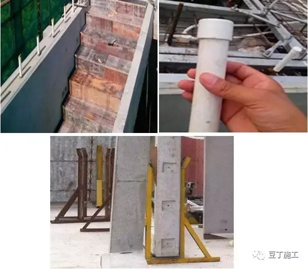
Upon arrival, prefabricated components are lifted by tower or truck cranes to dedicated storage areas, stacked on sleepers with anti-overturning measures. Wall panels are stored vertically, supported by channel steel at their bottom ends, and stacked orderly with spacers to prevent domino-like collapse. Temporary enclosures protect the site from human or mechanical impacts.
Product Protection
Protecting PC components during transportation, stacking, and lifting is critical. Steel frames are used to secure components during transit. Vehicles must maintain slow, steady speeds, especially when turning, to avoid damage. Soft materials such as cotton yarn or rubber blocks are placed between PC components and steel frames to prevent collision damage.
During stacking, steel poles maintain stability and balance. Sleepers, cotton yarn, or rubber blocks are placed beneath stacked components to keep them flexible and prevent damage to the lower BIM parts. Stairs, balconies, and similar components are stacked individually, with four evenly sized wooden blocks used as padding to protect exposed stirrups and edges. Plastic gaskets are positioned during fine-tuning to reduce damage during installation. PC structures must be covered with wooden boards during construction to protect finished surfaces. Sleeve connection anchor steel bars are shielded with PVC pipes before concrete pouring to prevent contamination.
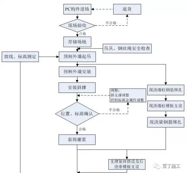
3. On-Site Construction of PC Structures
Construction Process
4. Lifting Plan for Prefabricated Components
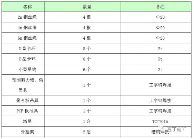
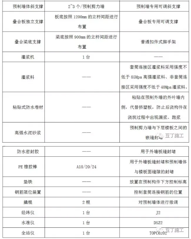
1. Materials Prepared for Hoisting
2. Lifting Construction Technology
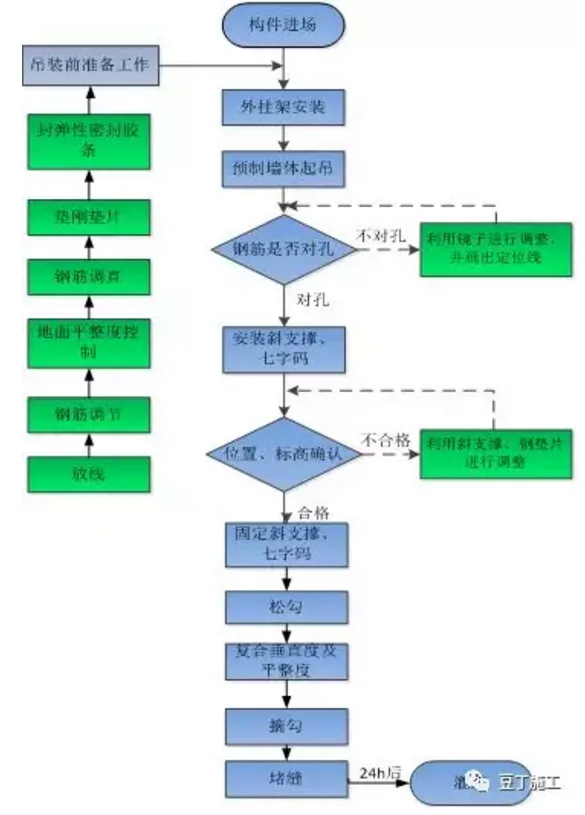
4.2.1 Hoisting Process for Prefabricated Walls
The lifting process includes the following steps:
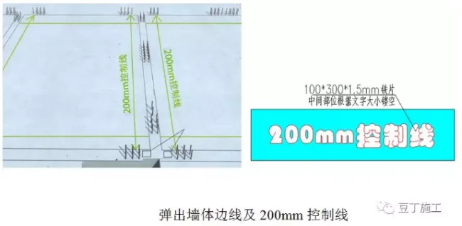
4.2.2 Preparation Before Lifting Prefabricated Exterior Walls
Clean joint surfaces thoroughly. Mark the prefabricated wall positioning edge line and a 200mm control line on the completed floor slab according to the positioning axis. Label the 200mm control line clearly on site to facilitate construction and wall alignment.
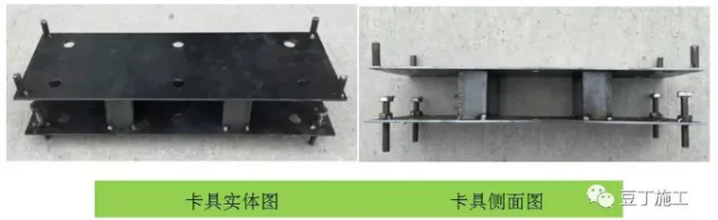
Check verticality, positioning, and height of steel bars using custom steel bar clamps. Correct any deviations to ensure sleeves on the upper exterior walls align smoothly with reserved steel bars on the next layer.
4.2.3 Prefabricated Exterior Wall Lifting
Two signal workers are assigned during lifting: one at the lifting site and one on the receiving floor. One hook operator manages the hoisting, while three workers on the floor place and secure the exterior wall.
Before lifting, the quality manager verifies the panel model and dimensions. After quality confirmation, a dedicated worker hooks the component. Once the hooker moves to a safe zone, the signal worker below confirms safety and initiates a trial lift to about 0.5 meters above ground. Upon confirming the crane’s safety, lifting proceeds.
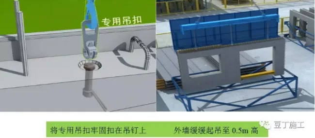
4.2.4 Prefabricated Exterior Wall Installation
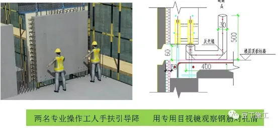
When the wall is lowered to about 0.5 meters from the floor, adjust its position using the pre-set guide frame and control lines, then slow the descent. Two skilled operators guide the wall manually. At 100mm above the floor, a worker uses a specialized visual mirror to check alignment of connecting steel bars with their corresponding holes.
(Lifting personnel on site adjust the component position per positioning and elevation control lines, prepare shims, and place components within control lines accordingly.)
4.2.5 Alternative Installation Method for Prefabricated Exterior Walls
Measure the elevation at the four corners where gaskets will be placed on each prefabricated exterior wall for the floor to be lifted using a level. Calculate the average elevation to determine the correct gasket placement height, adjusting for any significant differences between lowest and highest points.
Record the elevation of each point (a) and average elevation (b). After acceptance inspection of the prefabricated wall, obtain the inner leaf wall height (c) at the gasket position. Using the floor height (e.g., 2900mm), calculate the gasket height (d) as follows:
–(a – b) + d + c + 130mm = 2900mm
Example:
–(2848 – 2852) + d + 2753 + 130 = 2900
–(–4) + d + 2883 = 2900
d = 21mm
Before measurement, rough surfaces of gasket placement and contact areas must be manually leveled. The gasket’s lower contact surface should align horizontally with the inner leaf wall’s edge, adjusting for any protrusions or indentations during installation.
This method ensures horizontal joints between exterior walls align precisely, enabling optimal joint quality.
On-site acceptance requires that prefabricated exterior walls approximate a regular rectangle with vertical seams aligned within 2mm tolerance horizontally and vertically, meeting design standards.
After lifting the first floor, measure average elevation to control subsequent floors’ heights and overall building elevation. Minor elevation errors (e.g., 5mm) can be corrected incrementally with gasket adjustments or concrete pouring over subsequent floors.
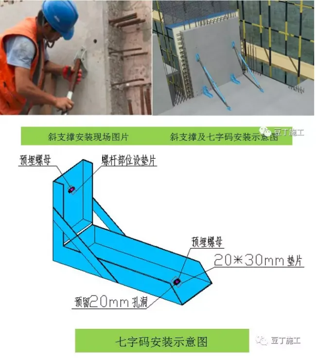
4.2.6 Installation of Support System
Once the wall is positioned, dedicated personnel install diagonal braces and “seven character” codes to fix and adjust the wall, ensuring verticality. Hooks are removed only after supports are secured. Prefabricated walls require embedded nuts for diagonal brace connections.
Two adjustable diagonal braces and two “seven character” codes are installed per wall to strengthen the connection to the main structure, preventing movement during subsequent operations.
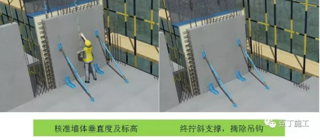
4.2.6 Position and Elevation Confirmation
Verify wall verticality with a ruler and elevation with a level. Adjust diagonal braces to achieve precise positioning, then secure them firmly.
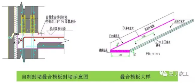
4.2.7 Sealing
Before sealing, clean debris around the wall and in gaps using a hair dryer. Use custom-made double-layer composite formwork (100mm wide, 30mm high) to seal the gap between the wall and floor. Attach a 3mm thick rubber waterproof sealing strip along the inner edge of the formwork. Secure the formwork with cement nails, ensuring no grout leakage during sealing.
5. Grouting Project
1. Inspection to Ensure Grouting Holes Are Clear
Since wall panels are stacked vertically on site, inspecting sleeve holes at the bottom is challenging; therefore, inspection is done at the manufacturing facility. After demolding, shine a flashlight through the sleeve bottom to check for foreign objects. Use compressed air or water to clear any blockages.
Rubber or wooden plugs protect sleeve holes during transportation and storage to prevent debris entry. Missing plugs must be replaced and sleeves cleaned with a pipe brush before lifting.
2. Inspection of Grouting Materials
(1) Strength Testing
Grouting materials must be batch-tested by floor, producing at least three specimens (40mm × 40mm × 160mm) per layer per work shift. After 28 days of standard curing, compressive strength tests are performed.
(2) Flowability and Operability Time Verification
Before each grouting operation, test the flowability and working time of freshly mixed material. Initial flowability should be ≥ 300mm, with 260mm as the minimum acceptable limit. Use a grouting machine to circulate material and record how long flowability remains above 260mm. Ensure grouting is completed within the operable time.
3. Determining Grouting Strength and Timing for Removing Temporary Supports
(1) Conduct tensile strength tests on grouted steel sleeve connections before producing prefabricated walls. Use at least three specimens per specification. Based on tensile and compressive strength reports, determine when grouting material meets design strength and when temporary supports can be removed.
(2) Use grouting materials and sleeves from the same manufacturer, matching design and sleeve specifications. Follow manufacturer preparation instructions strictly. Any replacement requires retesting to ensure compliance with design strength.
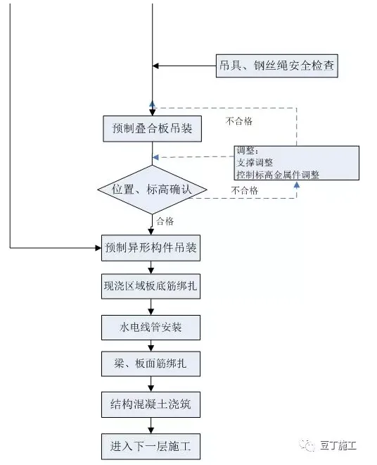
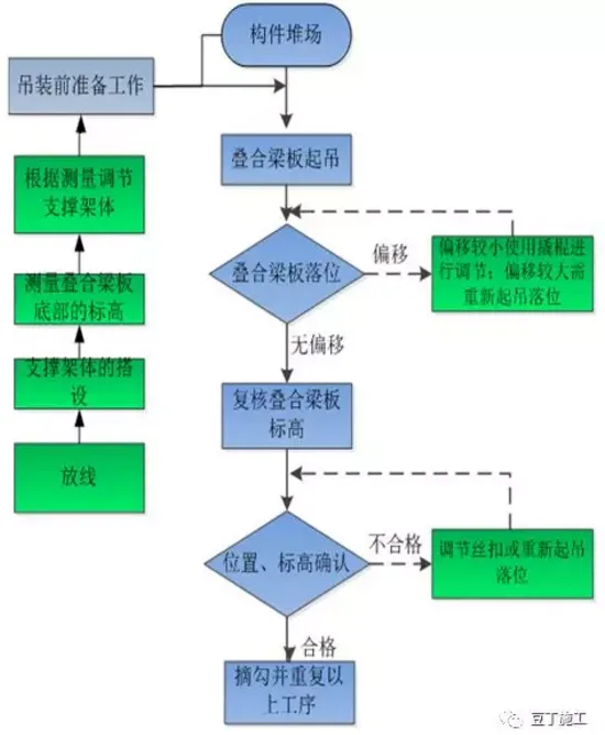
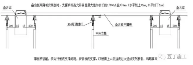
6. Lifting Technology for Composite Panels and Beams
Lifting Process Flowchart:
4. Dividing Grouting Areas into Compartments
Due to the large grouting areas and short initial setting times, manually divide grouting spaces to ensure manageable operations. Single compartments should generally not exceed 1 meter in length. After successful physical testing, this may be extended up to 3 meters.
Partition walls are placed between sleeve and non-sleeve zones, typically at the boundary between concealed columns and wall bodies. Larger walls are subdivided further. Partition walls are at least 2cm thick and positioned at least 4cm away from connecting steel bars to avoid obstruction.
Use easily removable PVC pipe liners for partition formworks. After filling sealing material tightly between components, remove liners to complete partitions.
5. Joint and Grouting Hole Sealing
Seal joint edges using a combination of sealing mortar and polyethylene rod strips. Place sealing strips at wall edges before hoisting. After installation, apply mortar to joints, press sealing strips inward, and fix formwork. Allow mortar to cure for at least 24 hours before grouting.
Moisten grouting surfaces before operation without allowing water pooling. Grout through lower sleeve holes, simultaneously filling multiple sleeves via connecting cavities. Use rubber or soft wooden plugs to sequentially block grout holes. Maintain pressure until grout is fully discharged and sleeves are sealed. Hold pressure for 5 seconds post-grouting to ensure compactness; immediately address any leakage.
6. Preparation Before Grouting
(1) Personnel Preparation
Grouting quality critically affects structural stability and must be performed by trained professionals. All personnel, including management and operators, must undergo training and comply with national standards. The grouting team typically includes one mechanical technician, one slurry preparer, one grouting operator, and one sealing worker.
(2) Material Preparation
Verify product certificates and factory inspection reports upon material arrival. Conduct trial mixing and grouting tests onsite to assess flowability and operability time. Store materials in dry, ventilated spaces protected from direct sunlight. Use grouting materials and sleeves from the same manufacturer, strictly following preparation instructions. Any substitution requires retesting for compliance.
Perform compressive strength tests per batch as described above.
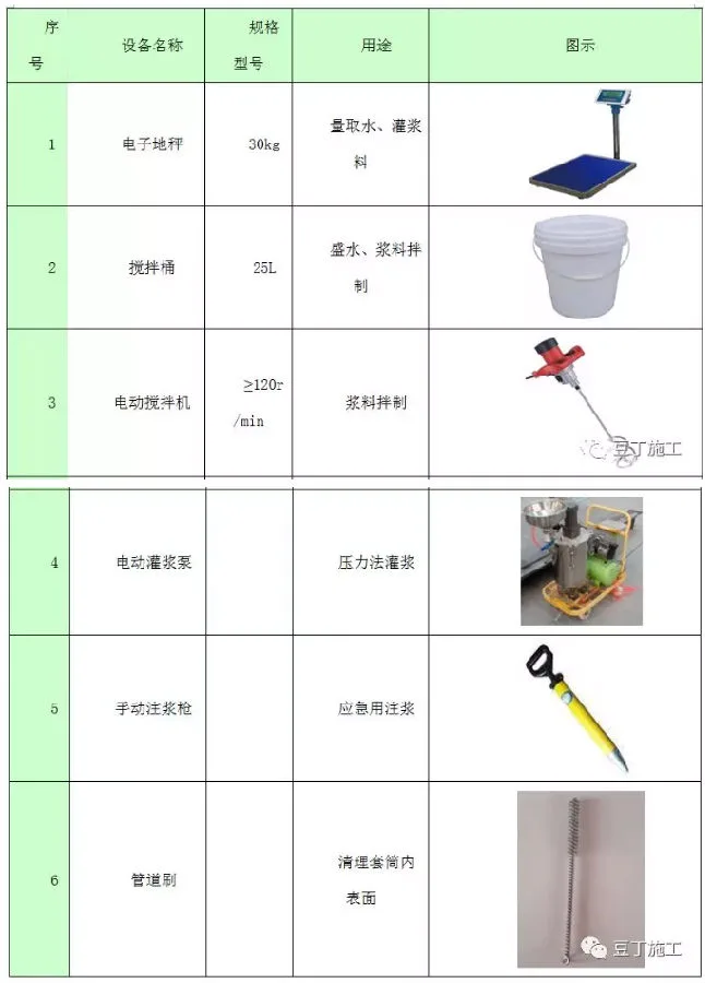
(3) Instrument and Equipment Preparation
1. Preparation Before Lifting
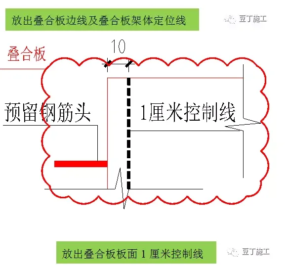
(1) Measure and mark dimension positioning and support pole lines on the lower slab surface before hoisting composite beams and slabs.
(2) Mark a 1cm control line at overlaps between composite beams, slabs, and precast or cast-in-place components.
2. Construction of Composite Beams and Slabs
During lifting, two signal workers are assigned: one at the lifting site and one on the receiving floor. One hook operator manages the hoisting, and two floor workers handle placement.
The quality manager verifies component numbers and sizes before lifting. After confirmation, a dedicated worker hooks the component. Once the hooker moves to safety, the signal worker confirms surrounding safety and directs slow lifting. At about 0.5 meters above ground, the crane confirms safety to continue lifting.
Lower the beam and slab to 0.5 meters above the floor, adjust position with guide frames and control lines, then lower slowly. Two operators guide the placement manually. At 100mm above the floor, a worker checks vertical alignment of edges with positioning lines.
7. Hoisting Process for Prefabricated Stairs
Lifting Process Flowchart:
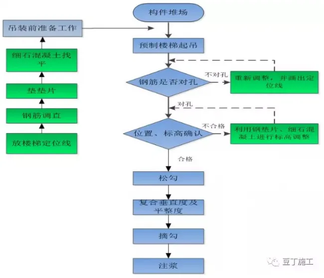
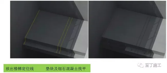
Preparation Before Construction
(1) According to construction drawings, mark stair positioning lines on the upper and lower landing platforms. Place steel gaskets on ladder beams’ surfaces and apply fine aggregate concrete for leveling. Gasket thickness options include 3mm, 5mm, 8mm, 10mm, 15mm, and 20mm.
(2) Inspect vertical connection steel bars and correct any misalignments.
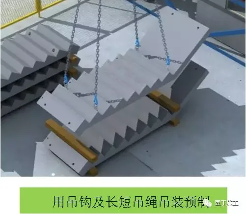
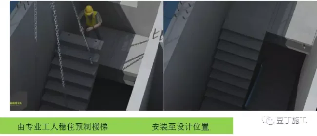
Prefabricated Stair Lifting
Use hooks with long and short ropes to lift stairs. Two signal workers are assigned during lifting, one at the component location and one on the receiving floor. One hook operator manages hoisting, with two workers on the floor to place and secure the stairs.
Before lifting, the quality manager verifies stair models and dimensions. After quality confirmation, a dedicated worker hooks the component. Once the hooker is in a safe area, the signal worker verifies safety and commands slow lifting to about 0.5 meters above ground. After crane safety confirmation, lifting continues.
Installation of Prefabricated Stairs
Lower the stairs to about 0.5 meters from the floor. Skilled operators stabilize and slowly lower the stairs following the horizontal control line, aligning reserved steel bars and placing the stairs in the designated position.
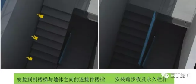
Install connectors between stairs and walls, step boards, and permanent railings. Embedded nuts in prefabricated walls secure connectors.
8. Support Systems for Prefabricated Components
Diagonal bracing on precast shear walls prevents overturning before grouting reaches design strength. Brace layout depends on wall dimensions, reinforcement placement, and embedded parts. Wall-side fixation uses embedded parts; floor slab fixation may require expansion bolts or embedded steel bar heads due to concrete pour processes.
Composite beams are supported by clip-type scaffolds, with elevation adjustments made via scaffold crossbars.
Wall composite floor slabs use custom triangular independent supports, vertically supporting slabs and cast-in-place sections during pouring. Pole support systems have two layers, with turnover every two layers: after completing layer x, remove supports there and install on layer x-2 for ongoing construction.
Support for cantilevered structures like balconies and air conditioning panels follows the same system, typically with three layers of triangular supports for turnover.
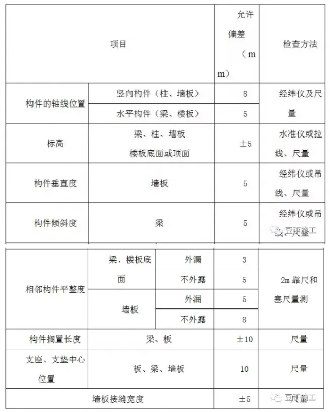
9. Quality Assurance Measures for Hoisting
Error tolerance table for prefabricated components during hoisting, installation, and connection:
Measures to Ensure Elevation and Verticality During Hoisting
Controlling elevation and verticality is crucial for efficient wall hoisting and overall progress.
1) Transfer elevation control lines onto protruding steel bars after concrete pouring.
2) Place shims based on elevation control lines, selecting thicknesses of 2-3mm as needed. Adjust shim quantity on site to meet elevation specifications.
Quality Control for Grouting
1) Use grouting materials that comply with design requirements and standards. A dedicated worker should manage each mixing batch.
2) Ensure every hole is fully filled; grout exiting exhaust holes indicates completeness. Follow user manual and specifications for mix proportions.
3) Record water usage per batch; do not exceed design limits.
4) Pre-wet grouting holes to avoid cracking from water absorption.
5) For long shear walls divided into segments, grout each segment promptly to prevent blockage. If blockage occurs, grout from alternative holes until full.
6) Clean all equipment immediately after grouting.
7) Avoid disturbance of walls for 24 hours after grouting.
8) Inspect each grouting hole after 24 hours; refill any unfilled holes.
Anti-Collision and Anti-Overturning Measures
Due to insufficient concrete strength at early stages, embedded expansion bolts may not achieve full strength. Strict control of lifting methods is required, avoiding collision with installed walls.
During lifting, tower crane operators and signalers coordinate precisely to guide panels. When panels are about 1 meter from placement, at least two workers on each side support and firmly position the panels.
If external wall diagonal braces have large spans, protective ropes must be installed diagonally between the top of the wall and embedded parts in the poured concrete to prevent overturning.
Workers must avoid contact with diagonal braces during construction to prevent injuries and ensure wall stability. Standing on the opposite side of installed braces is prohibited.
Supports under composite panels must remain until cast-in-place concrete reaches design strength.
Similarly, supports for prefabricated balconies and cantilevered panels must not be removed until concrete strength requirements are met.
Article source: Zhongtian Construction


Must log in before commenting!
Sign Up