1. Technical Features
With the advancement of society, there are increasing demands for safety, intelligence, comfort, and energy efficiency in buildings. This has resulted in a broad variety of mechanical and electrical systems, a complex network of pipelines, and increasingly limited installation spaces. Traditionally, two-dimensional software such as CAD has been used to create comprehensive mechanical and electrical drawings, often supplemented by sectional drawings to address pipeline integration challenges. However, the limitations inherent in 2D coordination mean that pipeline layouts frequently lack optimal rationality.
By leveraging modern technology like BIM, significant improvements in pipeline efficiency can be achieved. BIM technology enables 3D modeling of buildings and MEP (mechanical, electrical, and plumbing) systems. Through its powerful visualization and collision detection capabilities, BIM allows for the identification and resolution of pipeline integration issues by running collision checks on the information models. This enables timely adjustments, reducing unnecessary rework during construction, improving fire protection installation rates, and meeting high standards for elevation and build quality.
2. Implementation Process
(1) Integrated Pipeline Implementation Process
1. Establishing a BIM Team: To promote BIM Technology, a dedicated team of experienced engineers and BIM specialists is assembled. Their aim is to enhance the quality of MEP design and on-site construction through BIM model informatization.
2. Selection of BIM Software: Among various BIM applications, Revit stands out for its widespread use, comprehensive services, and economic advantages. As such, Revit is recommended as the primary software.
3. Equipment Configuration: BIM software demands high-performance hardware. Specialized computers and devices must be configured to meet these technical requirements.
4. Establishing a Family Database: A 3D family library of commonly used materials and equipment is created and continuously updated to meet the needs of different projects.
5. Project-Based Modeling: Using BIM software, 3D models of building structures and pipelines are developed based on 2D construction drawings for architectural and MEP systems.
6. On-site Structural Verification: Personnel conduct field surveys based on structural drawings, updating the building model as needed to reflect actual site conditions.
7. 3D Collision Detection: Collision checks are performed using BIM’s detection tools, with reports generated to identify and resolve conflicts systematically.
8. Construction Guidance & Prefabrication: The adjusted BIM model serves as the basis for factory prefabrication of some materials and for technical briefings prior to construction.
9. As-built Drawings: The BIM model is further refined to reflect the completed construction, ensuring accuracy in final documentation.
(2) Specific Steps in Integrated Pipeline Implementation
1. Comprehensive Pipeline Design Team: Our unit, in coordination with the chief engineer and construction manager, formulates detailed design and construction plans to ensure seamless integration between design and execution.
2. Division of Labor: The general contractor defines responsibilities, ensuring coordination between our team and the design institute. The design institute provides technical support and confirms detailed drawings, while our team produces comprehensive pipeline diagrams to guide construction.
3. Integrated Layout: All pipeline systems are consolidated into a single diagram, highlighting complex intersections and design conflicts. Adjustments are proposed to optimize routing and resolve conflicts through interdepartmental discussions, ensuring each pipeline is rationally placed within the building space. Detailed construction drawings are then produced, verified on site, and further refined to complete the final comprehensive pipeline plan.
4. Software Applications: Revit is used for in-depth pipeline design, with MagiCAD employed for areas with special requirements.
5. Comprehensive Pipeline Design Principles:
- Priority is given to large-diameter pipes (such as HVAC ducts, drainage, and exhaust pipes) due to their significant space requirements. Smaller, more flexible pipes are arranged subsequently.
- Temporary pipelines should avoid long-term pipelines.
- Pressure pipelines and non-pressure pipelines (like gravity drainage) must be arranged so that pressure pipelines do not obstruct gravity flow, maintaining necessary slopes for proper drainage.
- Metal pipes, which are easier to bend and connect, should be prioritized over non-metallic pipes.
- Electrical circuits should not be installed above hot water pipes or directly beneath water pipes to avoid exposure to heat or moisture.
- Fire protection pipes should not intersect with chilled water pipes of similar diameter, as chilled water pipes are insulated, offering process and cost benefits.
- Low-pressure pipes should avoid high-pressure pipes due to the higher cost of the latter.
- Weak electrical lines (telecommunications, cable TV, computer networks) are susceptible to electromagnetic interference and should not share cable trays with strong electrical lines, maintaining adequate separation.
- Pipelines with fewer attachments should avoid those with more, facilitating easier construction, maintenance, and replacement. Pipelines should be arranged in straight, parallel lines whenever possible, with sufficient space reserved for installation, maintenance, and supports.
6. Comprehensive Pipeline Layout Methods:
- Locating Drainage Pipes (Non-Pressure): These pipes must remain straight to maintain slope. The starting point should be as close as possible to the bottom of the beam, with elevations calculated along the slope towards the riser.
- Locating Air Ducts (Large Pipes): Due to their size, HVAC ducts require ample space and are typically positioned next. If drainage pipes exist above ducts, the ducts should be installed below them; otherwise, ducts are installed at the bottom of the beam to maximize ceiling height.
- Other Pipelines: Once non-pressure and large-diameter pipes are positioned, remaining pressure pipes and cable trays are arranged, taking advantage of their flexibility. Special attention is given to pipeline arrangement along walls, placing insulation pipes, metal pipes, and large pipes inside, while small, easily maintained pipes are placed outward for accessibility. Proper spacing between pipes and structural elements (not less than 100mm) is maintained to facilitate installation and maintenance.
3. Implementation Results
The adoption of BIM technology for integrated pipeline layout has notably improved the qualification rate of MEP management. It has expanded the scope for factory prefabrication, reduced on-site rework, promoted energy-efficient and green construction practices, and enhanced the installation quality of MEP systems.
4. Application Cases
By creating BIM models for buildings, structures, and MEP systems based on construction drawings, BIM technology enables detection of collisions between systems and identification of design issues. This ensures accuracy and consistency between architectural and structural drawings, avoiding rework or demolition caused by design conflicts during the construction phase.
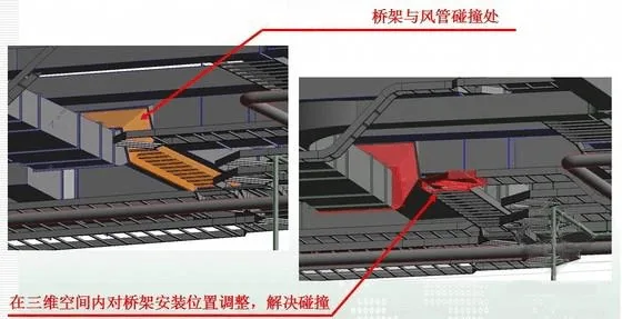
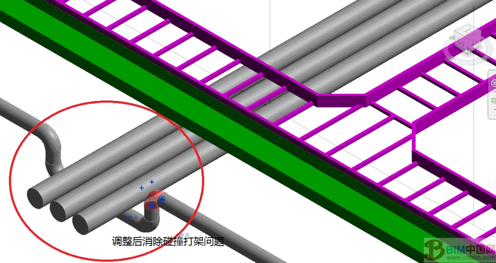
When the fire protection system conflicts with the MEP contractor’s air ducts, as shown in the image above, pipeline arrangement is based on BIM models of architecture, structure, and MEP. In case of any overlap or collision with the general contractor’s BIM model, coordination is carried out. Various discipline models are integrated into a single BIM model, and the software’s automatic collision detection function is used to identify and resolve conflicts among MEP systems as well as between MEP and architectural/structural elements. This approach allows for early problem-solving and efficient feedback for design coordination and modification.
From the image above, it is clear that the collision occurred at a prominent location. Through collision detection, a conflict between the cable tray and the air duct was identified, and, after negotiation, the cable tray’s position was adjusted to resolve the issue.
Utilizing BIM technology to detect collision issues between fire protection and MEP systems, as well as addressing design flaws, effectively ensures the consistency of architectural and structural drawings, preventing unnecessary rework and demolition during construction.
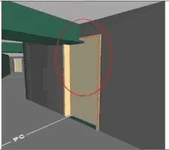
Collisions between structural beams and doors, as identified by BIM models, are difficult to detect in traditional 2D floor plans.
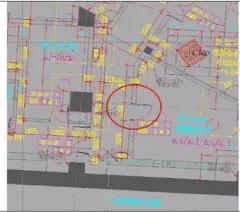
Case 1:
As shown in the diagram, a collision can be observed in the red-marked area. Pipeline routing needs to be adjusted to avoid this conflict. The blue area represents the air duct, which should avoid sharp 90-degree bends. The green area shows water pipes, whose positions are adjusted accordingly. All changes must pass collision checks before implementation to prevent construction errors.
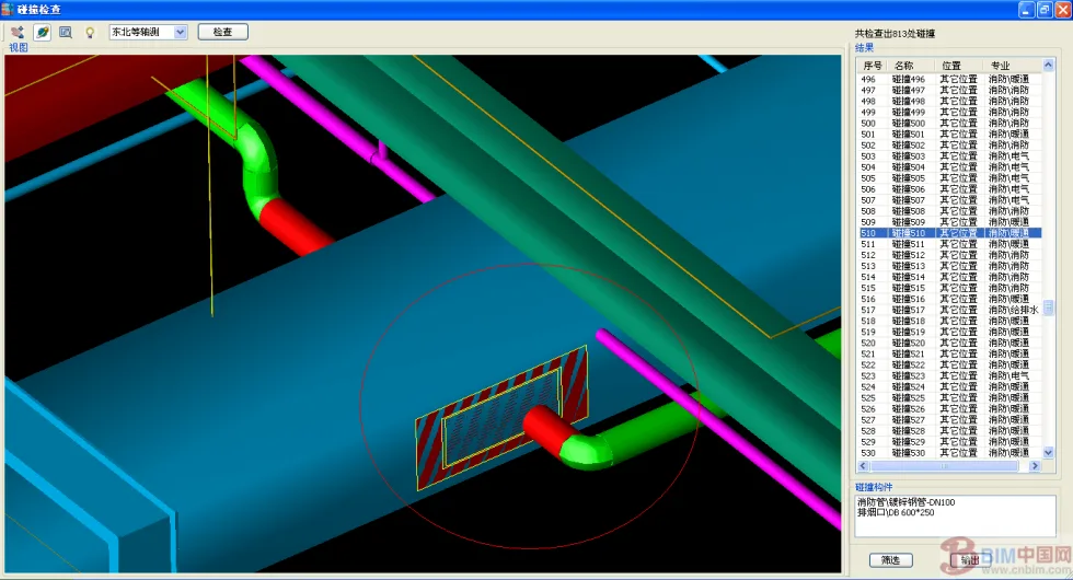
Case 2:
In the figure above, the light blue area is the cable tray, the green is the air duct, and the red is the fire water pipe. Collision inspection reveals two significant conflicts, marked by red circles: one between the fire cable tray and air duct, and another between the fire water pipe and other pipelines. Through BIM collision checks, these issues are effectively resolved. Large pipes should take precedence over small ones to avoid on-site clashes.
Reserved and Pre-Embedded Work
1) Main Process Flow
Reserved and pre-embedded construction involves several steps: reviewing and determining reserved embedded parts, processing and manufacturing them, familiarizing with drawings, detailed design, drawing reserved and embedded diagrams, preparing materials, and following the reserved and pre-embedded process flow chart.
2) Reserved and Pre-Embedded Construction
(1) All fire protection pre-embedded work for this project will be executed by the civil engineering department, with strict adherence to construction specifications and drawing requirements for acceptance.
(2) The reserved and embedded work mainly involves pipeline shafts, reserved holes and sleeves for floor penetrations, and sleeves for passing through partition walls. Control measures are enforced throughout the process, as illustrated in the table below.
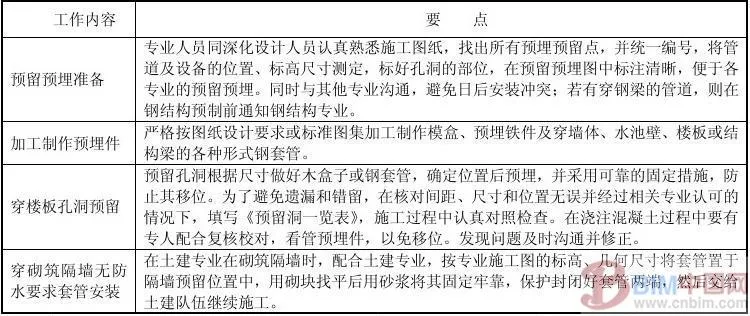
① When reserving holes, slots, or embedded parts in slabs, beams, and walls, a dedicated person measures and marks the location and elevation of pipelines and equipment according to design drawings. Prefabricated molds and embedded iron parts are fixed according to these markings before rebar binding.
Paper and similar objects should be stuffed into the box. During concrete pouring, a dedicated person checks and supervises the molds and embedded parts to prevent displacement.
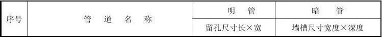
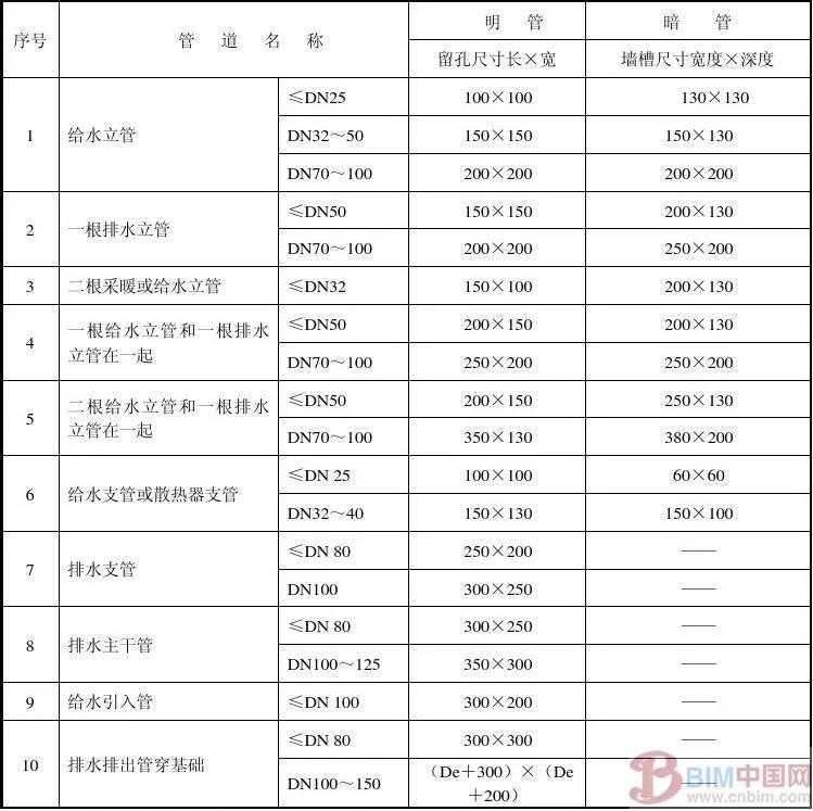
The groove depth in the wall for concealed pipes should be the pipe’s outer diameter plus 20mm; width should be the outer diameter plus 40–50mm. If there are no special design requirements, the size of reserved holes for other pipelines should follow the table below:
For hole works, pipeline shafts, penetrations through beams, and slabs must be coordinated with civil engineering, with strengthened inspections to prevent omissions.
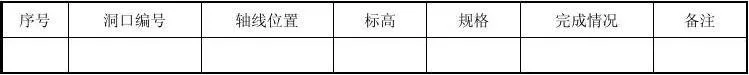
③ To avoid omissions or errors, after verifying spacing, size, and position and obtaining professional approval, a “Reserved Hole List” is completed and closely checked during construction. See the following table:
List of Reserved Holes
![]()
(4) Reserved and Pre-Embedded Casings
For core tubes and functional layers, reserved and embedded casings in partition walls are installed according to the following forms, methods, and requirements:
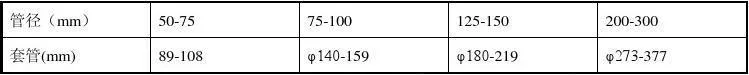
① The diameter of the casing is selected according to the standards listed in the table below:
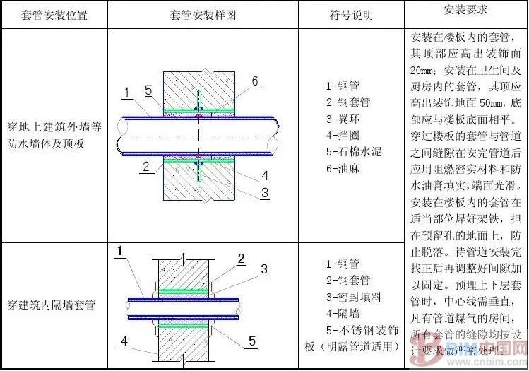
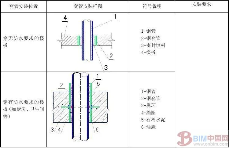
② The installation methods and requirements for casings are detailed in the following table:


Must log in before commenting!
Sign Up