A typical office building project in Beijing, with a total area of 100,000 square meters, utilizes the BIM platform. At this stage, due to the high hardware resource consumption, it is not feasible to design the entire project in a single model. Therefore, the above-ground units and the underground portion are modeled separately. The following sections will focus on the above-ground single unit.
By creating detailed lists, it becomes easier to count the quantities of various devices according to their system, function, and other parameters. Additional attributes such as elevation, model, current, and electricity can be added as needed. The switch details are calculated based on elevation, as illustrated in Figure 1.
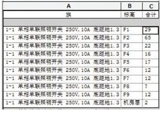
Figure 1: Switch Details Table
The fire alarm equipment details are calculated based on the total project quantity, as shown in Figure 2.
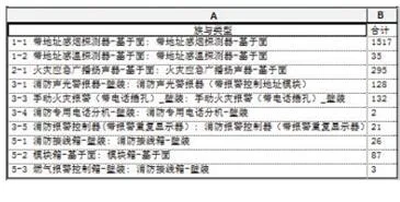
Figure 2: Fire Alarm Equipment Details Table
Cable tray information includes family name, type, size, length, and remarks. Figure 3 presents statistics for each section of the tray. For the same project and equipment, adjustments can be made by modifying the properties of the detail table, as shown in Figure 4. By deselecting the option to list each instance individually, the total length for each tray type with the same bridge size can be calculated, as displayed in Figure 5.
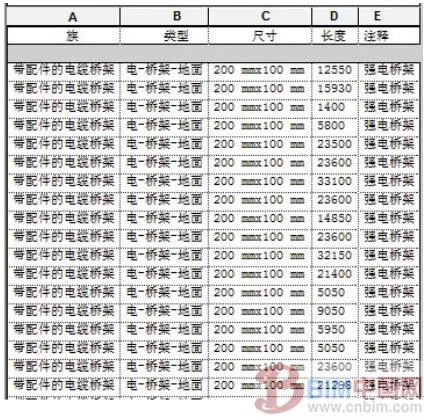
Figure 3: Bridge Structure Details Table
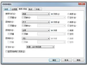
Figure 4: Detail Table Attribute Menu
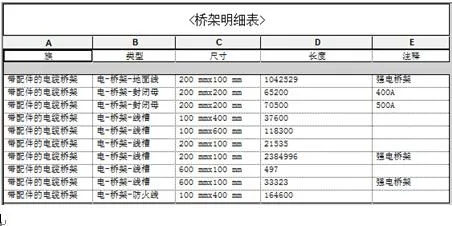
Figure 5: Adjusted Bridge Structure Detail Table
For some floors in this project, conduits were used instead of wires for electrical drawings. This approach makes the routing more logical and consistent with actual construction conditions, but increases the workload for designers. Drawing conduits requires determining the elevation, accurately selecting equipment connection points, and using numerous families as supports. Therefore, conduit drawing was applied in rooms with minimal conduit changes from the distribution box to the end, to compare the difference between model drawing quantities and actual usage, as presented in Figure 6.
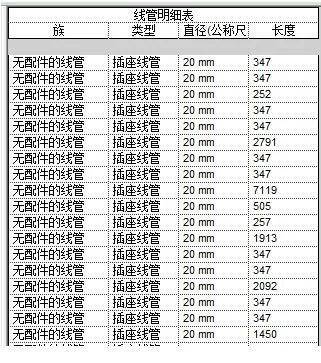
Figure 6: Line Pipe Details Table
BIM Application Advantages in Construction Management
Accurately determining the lengths of wires and conduits has always been a challenge in engineering quantity statistics and budgeting. With the API interface of the BIM platform, localized plugins can be developed to accurately count the engineering quantities of wires and conduits within a specific area. This greatly facilitates construction management and material preparation, as demonstrated in Figures 7 and 8.
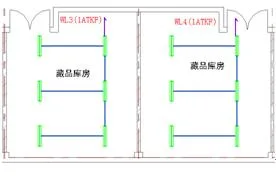
Figure 7: Statistical Region
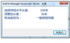
Figure 8: Quantity Statistics for Wires and Conduits in a Specific Area
For refined management and standardized factory production in the future, localized plugins can also accurately display the pipe lengths for all areas in the drawings, as seen in Figures 9 and 10. By enabling certain interfaces, it is possible to connect with factory production software, allowing wires and pipes to be produced in sections according to actual lengths. This avoids on-site cutting, saves significant resources and labor, and ensures accurate delivery of materials to relevant areas based on the construction plan.
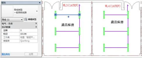
Figure 9: Statistics of Area and Line Pipe Length
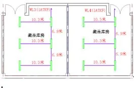
Figure 10: Segmented Pipeline Length Statistics in the Statistical Area
Conclusion
In this project, the calculated results were compared with those from the owner’s cost department. The error between the electrical equipment counted and the quantity calculated by Party A was within 1%, all due to human error. The error in cable tray engineering quantity was within 5%, because traditional two-dimensional calculations do not account for the quantities generated when the tray changes elevation, nor can they separately calculate accessories such as tees and bends. If cable tray accessories are included, the error is basically within 1%.
The greatest challenge lies in the calculation of wires and cables. At present, two-dimensional statistical results for wires and cables are not accurate. If all cable and wire attributes are fully input into the BIM platform model, the workload for electrical professionals would increase significantly. Considering current labor costs, it is not feasible to input all wire information into the building model, resulting in an error of about 10% compared to two-dimensional statistical results.
The CIFE Center at Stanford University in the United States has also collected statistical data from BIM applications across 32 American projects. Due to varying productivity levels, these figures are for reference only in China:
1) Eliminate 40% of budget changes and reduce material waste by 50%;
2) Cost estimation should be controlled within a precision range of 3%;
3) Shorten the total project duration by 7% and achieve investment return sooner.
In the foreseeable future, the application of BIM platforms, localized software, and third-party computing tools will undoubtedly bring revolutionary changes to the electrical discipline in engineering budgeting and construction management. These advancements will save significant resources and time, contributing greatly to the sustainable development of the engineering field and the construction of a resource-conserving society.
Authors: Zhang Enmao, He Lin
China Architecture Design Institute Co., Ltd


Must log in before commenting!
Sign Up