Source: Steel Structure Alliance
Project Overview
This project involves the construction of a grid greenhouse featuring a steel grid roof supported by upper chord bolt ball nodes. The primary materials used are steel pipes and bolt balls, assembled with high-strength bolts. The steel grid structure will be pre-assembled on the ground, then lifted into place using pull-out rods and grinders through a block lifting method.
Materials Specification
1. The grid members consist of high-frequency welded or seamless steel pipes, made from Q235B carbon steel as per GB700-88 standards for structural steel.
2. Welding materials include E43 series welding rods conforming to the national “Carbon Steel Welding Rod” standard GB5117.
3. All materials come with certified quality documentation (raw material list).
Construction Planning
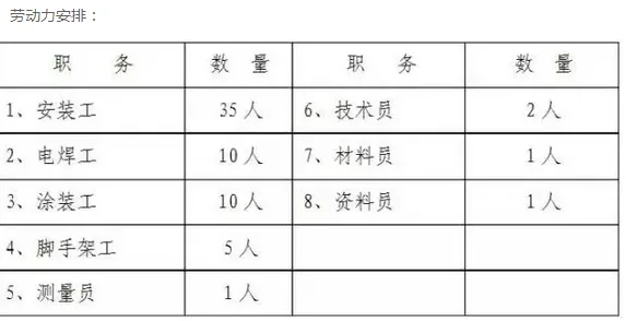
1. Workforce Arrangement
To ensure timely and high-quality completion, the construction team is divided into two groups: production and installation.
Factory Workshop Production: A dedicated team manages all aspects of grid structure production, including material supply, drawing review, sample fabrication, and material cutting. They oversee production readiness, technical coordination, quality control, and receive supervision from the owner, quality inspectors, and design teams.
2. Transportation Protection Measures for Finished Grid Components
(a) Storage and Handling: Components should be stored in ventilated, dry warehouses. If stored outdoors, protective measures against weather should be applied. Components must be handled carefully to avoid deformation or damage during loading, unloading, and storage. They should be organized by specifications and project numbers with clear labeling.
(b) Transportation: Rods are bundled and tied by number before shipment, and bolt balls are transported in iron cages. Both should be loaded onto heavy-duty trucks using cranes or shovels, stacked neatly to ensure safe transport.
(c) On-site Protection: Upon arrival, components must be neatly stacked by number on a level surface with rain and moisture protection. Dedicated personnel should supervise the storage area.
3. On-site Installation Workforce Deployment
Labor Allocation: Construction teams will operate according to the schedule set by the onsite construction management. Coordination ensures seamless transitions between tasks, and labor will be allocated flexibly to avoid delays.
Installation Methods
1. Method Selection
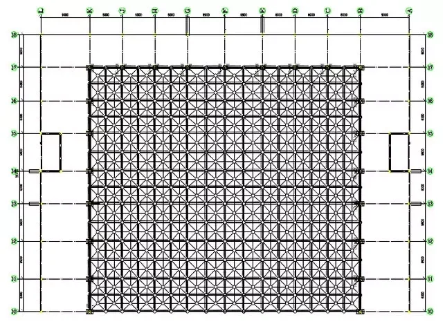
This project consists of three greenhouses (No. 1, No. 2, and No. 3). Taking Greenhouse No. 1 as an example, the structure is divided into two sections: 2-9/B-K and 10-17/B-K. Considering the large grid area and height, the installation method selected involves assembling the grid on the ground, then lifting it as a whole. This proven method offers several benefits:
- Shortened construction timeline and reduced vertical transportation costs of grid components.
- Lower safety requirements for workers assembling at ground level as opposed to working at heights.
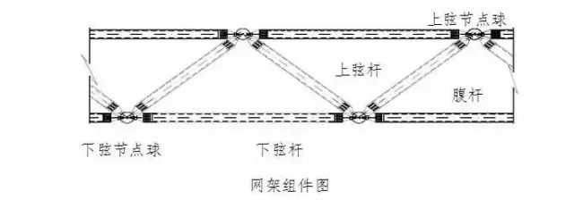
2. Grid Structure Assembly
a. Assembly Details
When assembling grid elements, ensure sufficient stiffness and geometric stability. Temporary reinforcements should be applied if needed.
Grid units are assembled from rods, bolt balls, and accessories. Workers assemble these into small units on the ground, extending the assembly from the center outwards, installing both upper and lower chords simultaneously. Installation dimensions are continuously tracked and verified.
After assembling all components on each bolt ball, bolts must be checked to ensure they are tight and secure, with temporary fixings applied to the lower chord. Bolt ball supports must be steady throughout. Before installing the next grid, recheck all high-strength bolts from the previous unit to ensure tightness. Once all components are installed, verify bolt ball nodes, measure axis alignment of upper and lower chords, check horizontal elevation and deflection—all deviations must fall within allowable limits.
Following this, assemble and install support brackets, tighten all support bolts, then remove temporary supports before proceeding to the next step. Each grid should be labeled for tracking from production through installation.
b. Assembly Sequence
Lower chord node → Lower chord member → Web member and upper chord node → Upper chord → Calibration → Bolt tightening
– Tighten high-strength bolts connecting lower chord balls and rods in one step.
– Assemble the belly bar and upper chord ball to form a downward quadrangular pyramid. Tighten all bolts connecting belly bar and upper chord ball. Only one of the three bolts connecting the lower chord of the belly bar is tightened initially to facilitate upper chord installation.
– Assemble upper chord members from the inside out, forming a downward quadrangular pyramid system. Tighten high-strength bolts sequentially.
During acceptance inspection, ensure longitudinal and transverse grids are connected with properly tightened high-strength bolts, treated according to steel structure anti-corrosion standards. Check for deviations in edge length, support point center offsets, and height discrepancies.
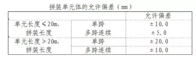
3. Inspection and Acceptance of Assembled Units
Quality control during unit assembly is critical for the overall grid installation. Strictly monitor assembly quality to ensure a solid foundation for the complete grid structure. Allowable deviations for assembled grid units are specified and must be adhered to.
Nodes and member surfaces should be clean and free from visible scars, mud, or dirt. Dimensions must be verified to be within allowable tolerances.
4. Installation Sequence for Grid Structure
The grid installation begins on the north side (10-17/B-K axis section), as illustrated:
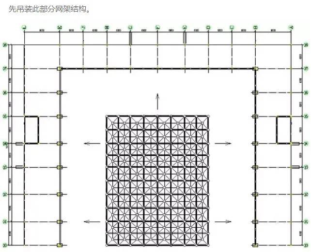
The installation proceeds from the center outward, simultaneously from all three sides. This approach creates multiple work fronts, accelerating progress.
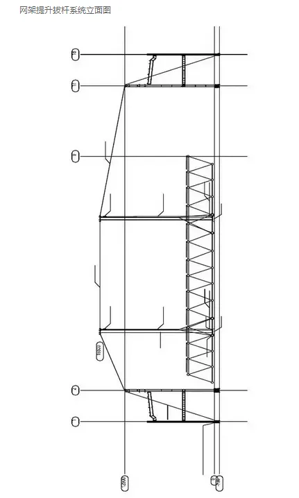
5. Grid Lifting Device Manufacturing and Installation
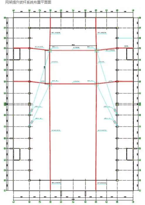
Layout of Grid Lifting Device:
(1) Lifting Rod Arrangement:
The grid structure weighs approximately 67.5 tons. Since some upper chord and belly members are installed after lifting, the maximum lifting weight is reduced to 62 tons. Four single-leg pull-out rods (426 × 10 mm in diameter and 16.5 meters long) will be used to lift the structure. Their layout is carefully designed to meet structural and safety requirements.
(2) Pole Arrangement Principles:
- Must not obstruct lifting or assembly.
- Ensure uniform force distribution.
- Foundations and support systems must be stable and secure.
(3) Grid Lifting Point Layout:
Dedicated crane operators are assigned to secure lifting points. Each connection must pass technical inspection before use. See the grid lifting point layout diagram for detailed arrangements.
(4) Grinder Arrangement:
Prioritize safety, command efficiency, and smooth rope guidance when positioning grinders. The layout can be locally adjusted to suit site conditions.
(5) Personnel for Grid Lifting:
Four grinders are required, operated by twelve personnel in total.
(6) Lifting Process Control:
The lift proceeds in three stages: first lifting to 1 meter, then pause to inspect for deformation; next lifting to 2 meters, pause and adjust for parallelism; finally, finish the lift if no issues arise. Each pause includes a minimum 30-minute observation.
6. Grid Lifting Verification
The central grid section is assembled on the ground and lifted using pull rods, with progressive lifting until the grid is positioned. Verification includes:
(a) Weight Calculation: Maximum pull rod lifting force Q’ = 15.5 tons (155 kN). Applying a safety factor of 1.2 results in Q = 186 kN.
(b) Load Calculation: Total load P = (Q + q) × K = (186.4 + 0.5) × 1.1 = 205.59 kN, where q (rigging weight) = 0.5 tons (5 kN), and K (dynamic load coefficient) = 1.1.
(c) Steel Wire Rope and Winch Selection: Pull force at rope end S = P/k1 = 205.59/6.73 = 30.55 kN, where k1 (mechanical efficiency of pulley system) = 6.73 (four quadruple pulleys with one guide pulley).
Using a safety factor of 5.5, the breaking force needed is 184.65 kN. A 22 mm diameter steel wire rope with a tensile strength ≥1770 MPa and breaking force of 273 kN is selected. A 5-ton winch will be used.
Grinder fixing: The grinder frame is secured to the steel column foundation with steel wire ropes.
(d) Pull Rod Base Calculation:
Vertical pressure on pull rod support Pc = P + Pt × sin 30° + G + T + S
- P = 205.59 kN (pulley force)
- Pt = 3.89 kN (cable tension)
- G = 16.93 kN (weight of pull rod)
- T = 2.92 kN (wind rope tension component)
- S = 33.57 kN (tension at rope end)
Calculated Pc = 260.95 kN.
Allowable ground bearing capacity is 160 kN/m², so the pull rod base area must be ≥ 1.63 m².
(e) Strength and Stability Verification:
The maximum deflection occurs at the midsection. Calculations confirm that the pull rod meets strength and stability requirements with a stability coefficient of 0.402 and a maximum stress of 68.75 MPa, well below the allowable 162 MPa.
(f) Lifting Lock Selection:
The sling force F = P / (4 × cos 45°) = 72.69 kN. Steel wire ropes of 18 mm diameter with tensile strength ≥ 1770 MPa are chosen, providing a breaking force of 182 kN (double strand 364 kN). The sling angle β is ≤ 45°, corresponding to a height h ≥ 1875 mm.
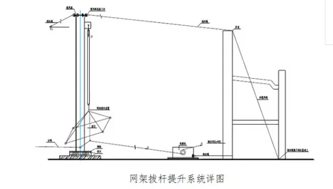
7. Manufacturing and Installation of Lifting Rods
(a) Base Treatment: No special base treatment is required at the construction site.
(b) Pull Rod Construction: Each single-leg pull rod consists of a steel pipe, base, pulley assembly, and winch. The top cable is fixed to the frame beam column, with all wire ropes tightened. Pulleys are installed at top and bottom, with grinder used for lifting. Pulley and cable specifications are carefully calculated. The top of the pull rod features a welded steel plate with clamp for cable attachment and a cantilever plate for suspending the lifting pulley. The bottom rests on square wood and is anchored to prevent displacement.
(c) Pull Rod Production: Steel pipes are transported to the site, measured, inspected, then assembled and welded. Pull rods are color-coded and labeled for management. After calibration and installation of pulleys and cables, the rods are ready for use.
(d) Pull Rod Installation: The rods are positioned on square wood bases and lifted into place using cranes. Cable wind ropes are tensioned and secured to steel columns. Additional tie ropes anchor the base to prevent lateral movement.
(e) Protection at Wire Rope Connections: Steel pipes are cut into three sections and placed at building corners to protect steel wire ropes from damage. At least four secure buckles are used for each rope connection.
8. Grinder Installation
Grinder placement is chosen based on site conditions and installed after lifting rods are in place. The grinder is secured to the building’s frame column with steel wire ropes, with lifting ropes wrapped around the grinder’s rolling shaft. The start switch is installed and connected to power, completing the setup.
9. Grid Structure Reinforcement
Load calculations consider self-weight, live loads, and wind loads, analyzed using SFCAD software. On-site reinforcement is applied at grid lifting points by welding two #8 channel steels to chord members, increasing cross-sectional area to prevent bending or deformation during lifting.
Construction Safety Measures
1. Production Safety Assurance
- Security department develops safety management systems aligned with national and provincial regulations. Clear responsibilities, safety indicators, and accountability measures—including rewards and penalties—are defined and enforced.
- Safety education is mandatory for all site personnel, promoting a safety-first mindset. Safety signs are posted, and a safety responsibility system is in place with regular assessments.
- The construction site is enclosed and isolated to protect surrounding roads and adjacent projects.
- A dedicated safety officer oversees safety system implementation.
- All personnel wear appropriate protective equipment, including helmets and safety harnesses for working at heights. High-altitude safety facilities are strictly maintained.
- Proper electrical installations are required; unauthorized wiring on the ground is prohibited.
- Site appearance and safety signage comply with regulations, with clear warnings for hazardous areas.
- Safety technical measures are developed and disclosed before operations, supervised by construction supervisors.
- Strict safety procedures govern all work, especially at “four mouth” protection points. Helmets and safety belts are mandatory, and non-slip footwear is required.
- Electrical distribution uses rainproof, dustproof mobile switch boxes with leakage protection and proper wiring segregation.
- Strict labor division and responsibility ensure site cleanliness, organized material storage, and protection against weather damage.
- Workers maintain clean footwear and tools are stored safely. Debris is promptly removed to prevent hazards.
- Strict enforcement of safety on-site: helmets must be worn; no slippers, heels, or plastic shoes allowed. Tools are stored in bags and accessed via designated routes. Welding is conducted away from flammable materials. Accident prevention is a priority.
2. Construction Safety Management
- A safety management team led by the project manager is established, combining specialized and group management.
- Hazard identification and risk assessments are conducted before construction, with preventive measures developed.
- Comprehensive safety management systems cover responsibilities, target management, inspections, education, technical planning, operation supervision, and incident reporting, with accountability linked to economic incentives.
- Safety education targets management and workers, emphasizing safety awareness and compliance. Personnel must be trained before working on site.
- Special operation personnel require valid certifications. Strict personnel management prevents unsafe operations. Helmets and safety belts are mandatory, with proper usage enforced.
- Regular safety inspections by the project department and site managers identify and rectify hazards promptly. Equipment and scaffolding must pass inspection before use.
- Pre-shift safety meetings and safety promotion encourage a culture of safety.
3. Grid Lifting Safety Measures
- A grid lifting leadership group is formed on-site, led by the chief commander. Four teams of three operators each are assigned, with a dedicated operator managing the grinder control switch.
- Essential materials such as spare steel hook bolts, steel wire ropes, buckles, wooden blocks, ropes, and an electric winch are prepared in advance.
- The site commander oversees all lifting operations.
- Operators must remain alert and stationed at their posts. No unauthorized personnel or pedestrians are allowed near or under scaffolding during lifts.
- Safety warning tapes delineate restricted areas with perimeter inspections conducted by two appointed inspectors.
- All lifting equipment is thoroughly checked before use to ensure proper operation.
- Lifting slings, electrical equipment, and tools undergo inspection; defective slings are replaced immediately to eliminate hazards.
- Lifts are not performed unless the command signal is clear, safety devices are functional, lighting is adequate, and wind conditions are safe (below level five).
- Dedicated personnel supervise all anchor points, reporting any issues immediately and halting lifting for reinforcement if needed.
- Rope fastening is monitored continuously; any loose or damaged parts are replaced without delay.
- Each pull rod is supervised for tilt; lifting stops immediately if any tilt is detected until corrected. Synchronization of lifting ropes is maintained, with adjustments made if height differences exceed 250 mm.
- Support frames or square timber are installed at both ends of the grid during lifting to provide stability.
- The grinder’s brake system must be responsive and reliable. In case of power failure, the brake is engaged immediately to lock and support the grid structure securely.


Must log in before commenting!
Sign Up