In recent years, China has actively promoted prefabricated buildings, leading to the gradual maturation and widespread adoption of prefabricated construction technology in residential projects. However, its application in public buildings remains largely experimental.
As pioneers in prefabricated construction, Huayang International and Vanke Group bring over a decade of experience in industrializing prefabricated construction technology, product development, and project implementation. Their portfolio includes landmark projects such as Vanke’s Fifth Residence and the Vanke Residential Industrialization Research Base.
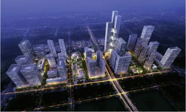
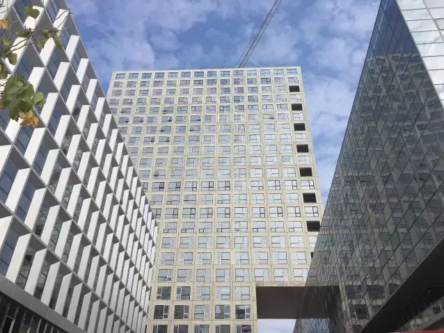
Aerial View of Vanke Cloud City
Since 2014, the two companies have embarked on a milestone project: Phase I of Vanke Cloud City. This marks the first large-scale prefabricated high-rise office complex in Shenzhen, aiming to explore the use of prefabricated concrete technology in office buildings within an era dominated by glass curtain walls.
Currently under construction, Building 8-B was topped out in September last year, becoming China’s first fully enclosed precast concrete (PC) office building.
In the March issue of Architectural Techniques, Wang Chuncai (Deputy General Manager of Huayang International’s R&D Department and Deputy Chief Engineer of Dongguan Industrial Park Company), Zou Xingxing (Architect at Building Industrialization Company), and Long Yufeng (Vice President of Huayang International Design Group and General Manager of Building Industrialization Company) co-authored an article titled “Practice of Prefabricated Office Buildings on Plot 03 of Vanke Cloud City Phase I.” The article discusses key considerations for controlling the application of prefabricated technology in high-rise office buildings, focusing on design, production, and construction aspects.
Huayang International’s official media will share insights from this article in two parts.
Project Overview
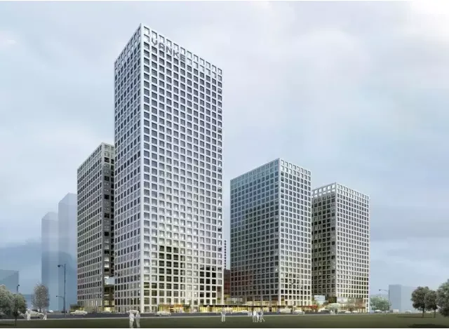
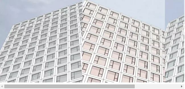
Rendering of Vanke Cloud City Phase I Plot 03
Vanke Cloud City Phase I is situated within the strategic emerging industry headquarters base of Liuxiandong, Shenzhen. This urban complex integrates apartments, industrial buildings, commercial spaces, and public activity squares. It is also Shenzhen’s first large-scale prefabricated high-rise office building complex. The site is bordered by Chuangke Road to the west, Liuguang Road to the north, and Liuxin South Road to the south.
The project employs an internal casting and external hanging system. All exterior walls use prefabricated components, stairs are prefabricated, the main structure is constructed using aluminum formwork cast-in-place methods, and interior partition walls utilize lightweight concrete slabs. Assembly techniques include self-climbing frames. The prefabrication rate is approximately 17%, with an assembly rate of about 60%, according to Shenzhen’s calculation standards.
Prefabricated Building Design
1. Standardized Design
Residential prefabricated projects often face challenges standardizing openings and depths across various functional layouts. Additionally, facade design requirements can lead to numerous component variations.
In contrast, prefabricated office buildings feature more regular structures, allowing for better control and standardization through the following design strategies:
- Unify the X and Y axis grid sizes, setting component widths based on grid spacing to ensure consistent component widths.
- Standardize floor heights, determining component heights accordingly for uniformity.
- Standardize cross-sectional dimensions of structural columns and outer ring beams to ensure consistent horizontal and vertical connections between components and the main structure.
- Design component shapes based on the building’s overall form, using regular repetition of single or multiple components to create rhythm and achieve the concept of “fewer specifications, more combinations.”
During the early design phase of Vanke Cloud City, prefabricated building technology planning determined the use of an internal casting and external hanging system, with precast concrete exterior walls.
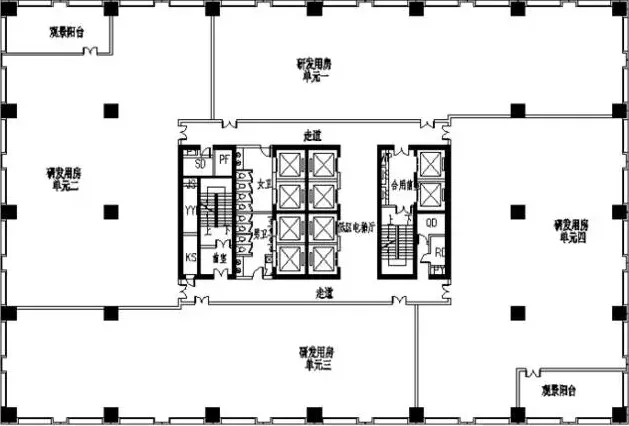
Standard Floor Plans for Blocks 7A, 7B, 7C, 7E, and 7F
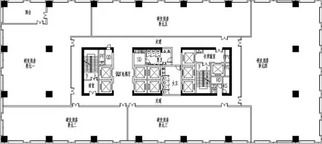
Standard Floor Plan of Building 8B
Given the similar layouts of the standard floors in six prefabricated buildings, a unified design was implemented: a standard axis grid of 8800mm, floor height of 4000mm, and outer ring beam section of 500 × 800mm. This resulted in standard and corner components available in three different specifications.
2. Facade Design
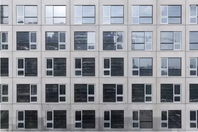
The facade of Vanke Cloud City adheres to the principle of “fewer specifications, more combinations,” aiming for a clean, simple, and elegant appearance. A unified prefabricated exterior wall system was established to embody the “Cloud City” concept.
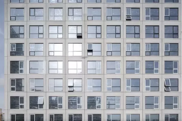
Diversity is achieved through variations in window designs within standardized facade units, employing techniques such as “deep windows,” “flat windows,” and “slanted windows” to add visual interest.
- The west facade features “deep windows,” combining shading and style with pronounced horizontal and vertical lines. The window recesses provide shading, supporting the project’s green energy-saving objectives.
- The inner courtyard facade uses “flat windows” to promote visual connectivity between indoor and outdoor spaces, sharing the rich landscape of the atrium.
- The remaining facades incorporate “slanted windows” that tilt to create dynamic light and shadow effects, enlivening the otherwise regular facade.
The project highlights the natural texture of concrete with a smooth, elegant finish. Combined with the interplay of light and shadow from the window elements, it expresses the industrial beauty of precast concrete architecture in its purest form.

Prefabricated Concrete Exterior Walls vs. Glass Curtain Walls
Compared to glass curtain walls, prefabricated concrete exterior walls offer distinct advantages:
- Facade Variety: Concrete’s plasticity allows for diverse surface patterns, textures, reliefs, and material variations, enabling rich facade compositions through orderly combinations.
- Factory-installed Windows: Windows can be prefabricated and installed with high waterproof performance, reducing urban light pollution.
- Durability: The building envelope system offers excellent longevity.
- Cost-Effectiveness: Lower initial costs than glass curtain walls, with reduced maintenance expenses over time.
3. Component Design
During conceptual design, the team standardized the grid layout, floor height, and outer ring beams, resulting in only two types of prefabricated exterior wall components: standard and corner components.
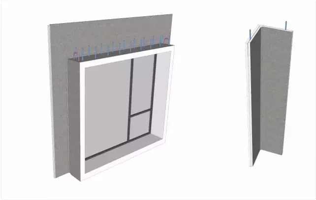
Schematic of standard component (left) and corner component
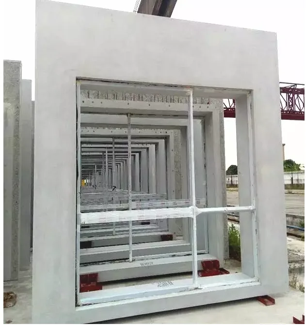
Completed prefabricated standard components
Within the 8800mm column span units, the exterior wall is divided into two standard components measuring 4380mm (width) × 3980mm (height) × 600mm (depth), weighing approximately 4.63 tons each. A total of 5,816 units were produced, with a combined volume of about 10,771 m³.
Due to variations in embedded window types—such as flat, recessed, inclined windows, and balcony railings—and slight differences in embedded construction points, component designs vary slightly. Corner elements are L-shaped, measuring 740mm (length) × 740mm (width) × 3980mm (height), weighing about 1.44 tons each. There are 608 corner components totaling approximately 350 m³ in volume.
Early architectural coordination minimized the types of exterior wall components, enhancing repetition rates and mold turnover, thereby reducing production complexity and costs.
4. Connection Node Design
The project’s main structure is a frame shear wall system with an internal casting and external hanging approach. Prefabricated exterior walls serve as non-load-bearing components, not contributing to the main structural forces. The top reinforcement of these walls connects to structural beams, sides connect to the main frame, and the base remains unconnected.
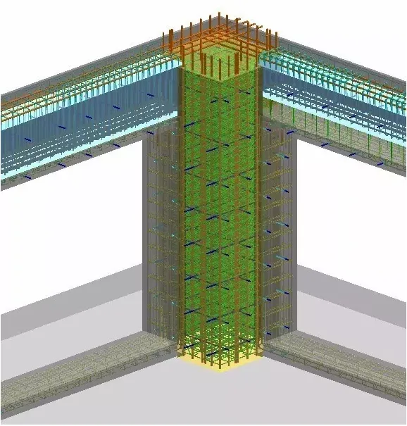
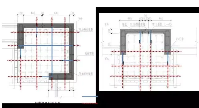
Schematic of connection nodes for prefabricated components
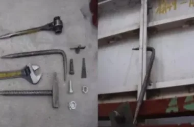
Components are fixed at junctions between prefabricated exterior walls and cast-in-place columns using aluminum formwork. Bolt sleeves are embedded in the components, and tension screws secure the aluminum formwork onsite. A custom-designed two-stage twin-screw system allows some twin-screw members to be embedded within concrete components for column connection, while others are reusable after mold removal.
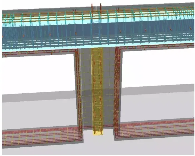
Schematic of the tension connection node between components and aluminum formwork
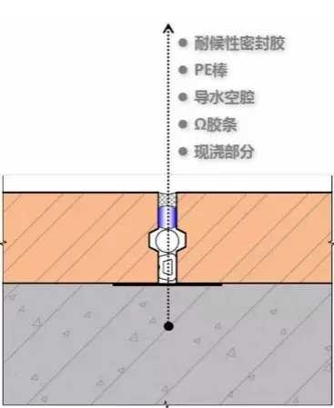
5. Waterproof and Leak-Proof Grout Connection Design
The waterproofing strategy integrates material waterproofing, structural waterproofing, and joint waterproofing.
Horizontal joints use tongue-and-groove and stepped connections, while vertical joints incorporate cavities and drainage pipes to ensure reliable waterproof performance of the exterior walls.
Given the large cross-sections of beams and columns, the tall floor heights, and the high lateral pressure during concrete pouring, there is increased risk of concrete expansion and leakage. To mitigate this, the node design includes leak-proof adhesive tape at vertical joints, steel plates connected with temporary PVC pipes (which are inserted into vertical joint channels during pouring and removed afterward), and thin aluminum sheets at structural columns densely reinforced with steel bars. These measures reduce the risk of leakage caused by lateral concrete pressure.
Vertical seam waterproofing nodes between components


Must log in before commenting!
Sign Up