China Zun Building presents many challenges in detailed design due to its unique shape, complex structure, and numerous integrated systems. High levels of coordination between various specialties are essential. Throughout construction, all disciplines employ BIM technology for detailed design, enabling deep integration of BIM into the construction process. This approach ensures full collaboration among all stakeholders, seamless professional cooperation, comprehensive process simulation, and application across the entire project lifecycle.
1. Overview of the China Zun Project
1.1 Introduction to China Zun
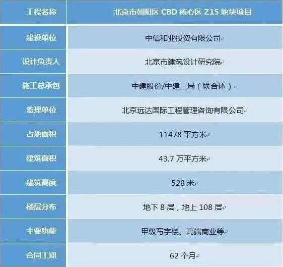
Situated in the heart of Beijing’s Central Business District (CBD) along the East Third Ring Road in Chaoyang District, the project covers a total land area of 11,478 square meters. It borders the planned Jinhe East Road to the east, Jinghui Street to the south, Jinhe Road to the west, and Guanghua Road to the north. The main tower is a multifunctional structure combining Grade A office spaces, high-end commercial facilities, and other uses. The project is developed by CITIC Heye Investment Co., Ltd. Upon completion, it will host the headquarters of CITIC Group and CITIC Bank, as well as attract major international financial institutions and Fortune 500 companies. Details can be found in Table 1.
1.2 Project Characteristics
The project’s complexity is evident in its site layout, construction schedule, vertical transportation, and safety management challenges.
1.2.1 Limited Site Space
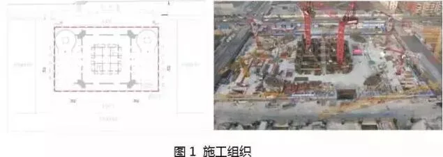
Located in the CBD core area, the project covers only 11,478 square meters. The building boundary lies just 10 cm from the land red line, meaning there is virtually no onsite construction space. This presents significant organizational challenges, with nearly all materials processed off-site. The site plan is illustrated in Figure 1.
1.2.2 Construction Progress
Progress is measured by monthly developed floor area. Except for the Shanghai World Financial Center (7,000 m²/month), most similar projects achieve between 4,000 and 5,000 m²/month. China Zun aims for 7,400 m²/month, positioning it as the fastest super high-rise construction project upon completion.
1.2.3 Vertical Transportation Challenges
Super high-rise buildings are essentially “three-dimensional blocks.” Buildings over 300 meters tall pose significant challenges in transporting personnel and materials vertically. China Zun’s main structure reaches 528 meters, with limited working surface area. The organization and speed of vertical transportation during construction are critical. To address this, four JUMPLIFT elevators were used to continuously elevate the elevator machine room to 500 meters during structural work. This effectively brought the formal elevator system online early, solving vertical transportation constraints during construction.
1.2.4 Construction Safety
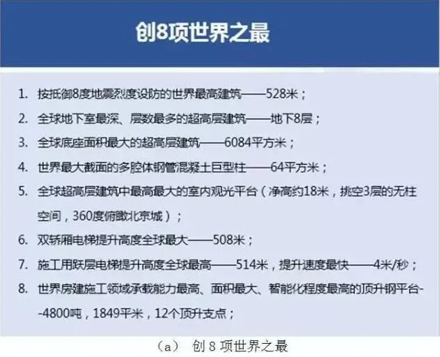
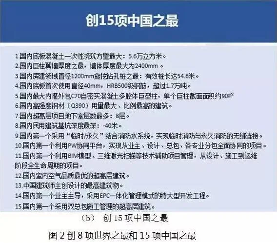
Safety is strictly managed during peak construction, when up to 4,000 workers are onsite. Robust safety protocols have enabled the project to set 8 world records and 15 Chinese records, as illustrated in Figure 2.
1.3 Current Progress
To date, the concrete structure has reached 105 floors, approximately 503 meters tall. Typically, super high-rise construction employs uneven height climbing: first building the core tube, then the outer tube, creating working surfaces for curtain wall and interior work. However, as shown in Figure 3, China Zun maintains minimal height difference between core and outer tubes due to its tight schedule. The overall progress depends less on core tube speed and more on creating multiple working surfaces for interior mechanical and electrical installation and finishes once the outer tube and curtain wall are completed. This enables balanced construction pace across all trades.
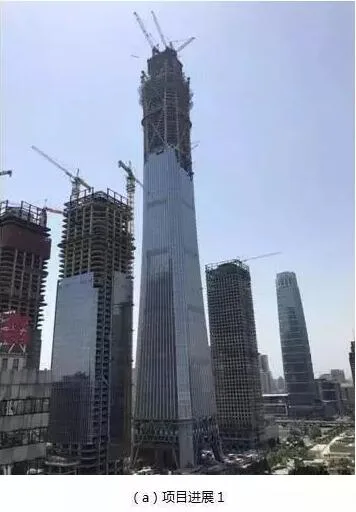
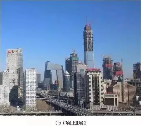
Figure 3: Engineering Progress
1.4 BIM Technology Integration
1. BIM integrates all information needed throughout the building’s lifecycle — from planning and design to construction and operation. This efficient 3D model-based data transmission accelerates progress, shortens timelines, and reduces costs. It supports energy savings, emissions reduction, and green construction while laying a technical foundation for digital building management during operation. Figure 4 illustrates BIM applications across project stages.
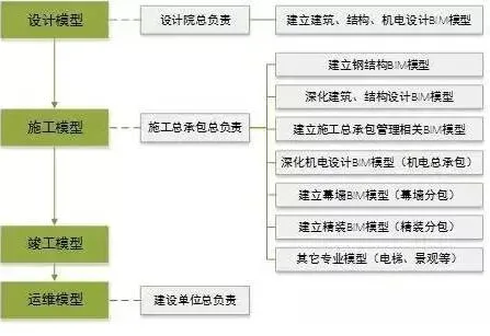
Figure 4: Continuous BIM model transmission and effective integration
2. China Zun is the first project in China to implement BIM technology fully from the design phase. Led by Beijing Institute of Architectural Design and Research, a dedicated team delivers both 2D and 3D designs, submitting BIM models within two weeks of 2D blueprint delivery. During construction, the BIM model supports detailed design, enabling all engineers and contractors to work on a standardized BIM platform. Over 100 BIM technicians have been involved to ensure seamless integration of all specialties.
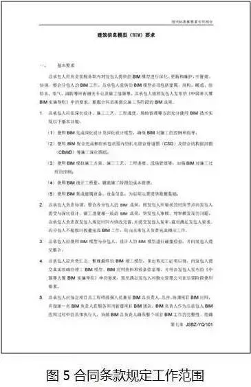
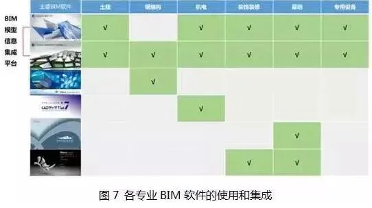
The project mandates BIM use from all participating units throughout the lifecycle. BIM scope is contractually defined (see Figure 5), and “BIM Implementation Guidelines” (see Figure 6) standardize BIM operations. Early project analysis identified six main software platforms used across disciplines, requiring a unified platform for model integration (see Figure 7). Since national regulations were lacking, the project developed its own BIM guidelines to ensure consistent standards, facilitating later operation and maintenance.
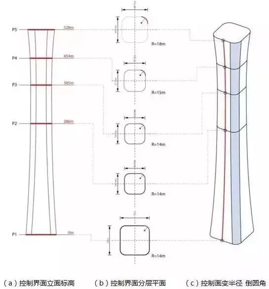
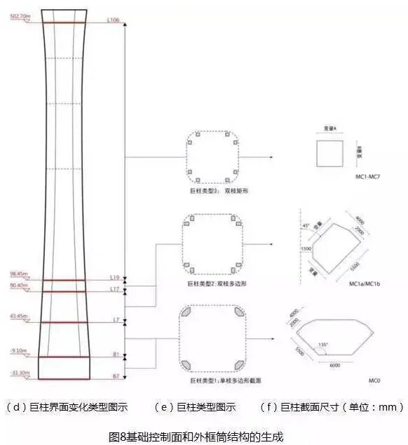
The ancient Chinese ritual vessel “Zun” inspired the building’s hyperbolic shape, lacking standard floor layers. The structural system uses a giant frame, with complex ring truss positioning connecting large columns. Early design was based on the building skin system, gradually coordinated with structure. The curved form demands high precision in engineering and control. Software and geometric control systems generate building forms, systematically capturing all geometric data to ensure accurate design, detailing, fabrication, and installation. Figure 8 shows the generation of control surfaces and outer frame structures.
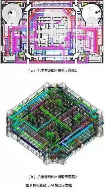
Given the project’s scale, BIM models are divided by systems, specialties, zones, and floors. Figure 9 illustrates how BIM technology coordinates and optimizes mechanical and electrical pipeline layouts.
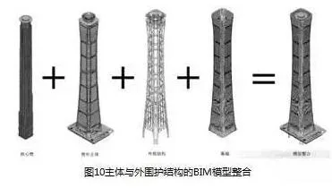
During design, a BIM model aligned with construction drawing depth is developed, supporting drawing and enhancing design communication. Figure 10 shows the integrated BIM models of the decomposed core tube, outer body, outer frame structure, and curtain wall.
BIM technology fosters early-stage professional collaboration. While interdisciplinary cooperation exists without BIM, its use deepens coordination, especially among mechanical, electrical, architectural, and structural teams.
2. Green Construction
During the China Zun project, green construction has been understood as more than reducing environmental pollution, using eco-friendly materials, and saving energy. BIM technology has played a subtle but critical role in aspects like construction drawing review and optimization, detailed design, prefabrication, comprehensive model coordination and clash detection, key construction planning, process simulation, 3D laser scanning, and model lightweighting.
2.1 Construction Drawing Review and Optimization
BIM transforms traditional construction workflows by enabling construction teams to intervene early, providing optimization suggestions for design and construction drawings based on BIM models. This reduces errors in drawings. Figure 11 demonstrates adjustments made after the involvement of two construction units.
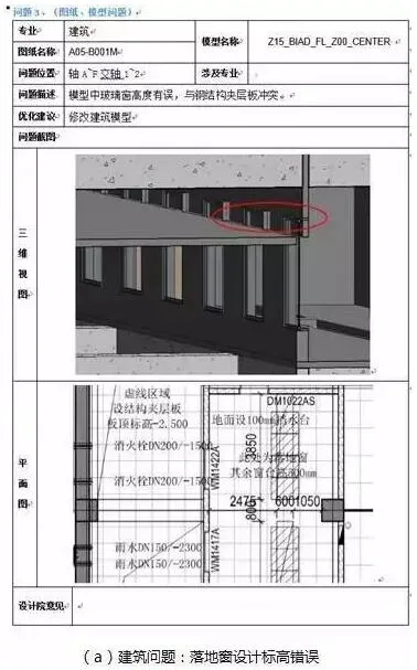
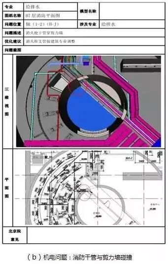
Figure 11: Example of construction unit’s optimization suggestions for design and construction drawings
By the end of 2015, five rounds of design submissions were reviewed. For the underground portion alone, owner, consultant, and construction units raised 11,981 comments. BIM review sessions addressed 4,959 design problems (about 41%). This significantly reduced waste, delays, and cost overruns caused by clashes, demolitions, and equipment mismatches. Figure 12 shows the proportion of effective deepening design drawings per discipline and compares issues resolved via BIM and traditional 2D reviews. BIM excels in quickly identifying problems invisible in 2D plans.
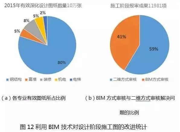
BIM’s advantages in detailed design are twofold: first, comprehensive application across structural, mechanical, curtain wall, and finishing disciplines allows simultaneous site work; second, it adds significant value to construction drawing development.
2.2 Steel Structure
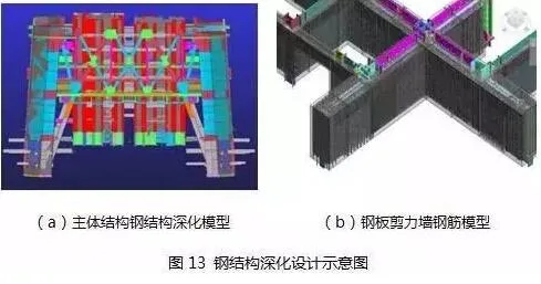
BIM supports detailed design, material fabrication, and component production for steel structures. Typically, design institutes do not provide component fabrication drawings, especially for complex elements like steel plate shear walls with intricate steel bar and plate interactions. BIM enables layout, perforation, and connector reservation within factory models. Figure 13 illustrates steel structure detailed design.
2.3 Secondary Structure
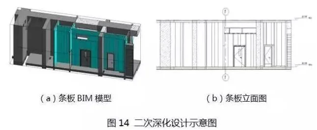
BIM is used for detailed design of secondary structures, working closely with mechanical and electrical engineering to design ring beams, structural columns, and reserved openings. Figure 14 shows interior partition walls made of ALC (autoclaved aerated concrete) strip boards, common in prefabricated buildings. Due to their dimensions, ALC boards require onsite assembly, necessitating detailed layout design for coordination. Similarly, block construction involves ring beams and structural columns requiring detailed planning.
2.4 Mechanical and Electrical Engineering
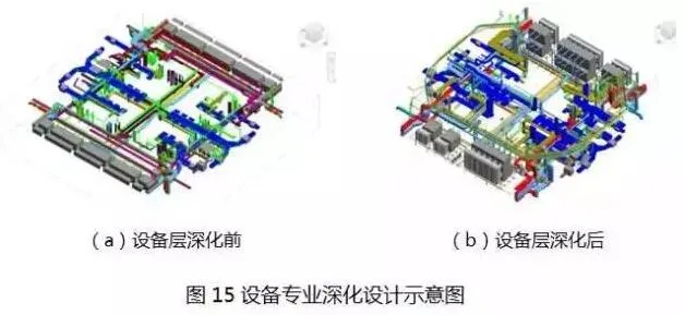
MEP teams deepen design based on initial models, producing detailed models of equipment aligned with procurement. Figure 15(a) shows design-phase BIM models, while Figure 15(b) displays construction-phase refinements. Equipment models are often finalized during construction, enabling true collaboration. Historically, equipment arrival onsite often led to route changes and incompatibility with previous reservations, causing wasteful rework. Early equipment confirmation and detailed design prevent such issues.
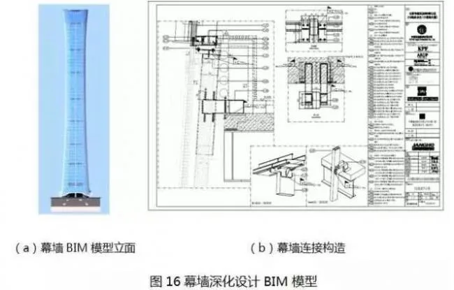
2.5 Curtain Wall Specialty
BIM confirms unit panel separation and positioning, guides construction drawing preparation, and generates curtain wall processing models for CNC machining. Curtain wall accuracy reaches LOD400 or higher, as shown in Figure 16.
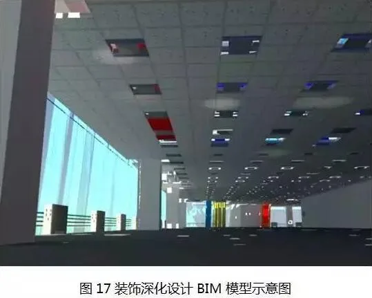
2.6 Decoration
The decoration discipline uses BIM to produce plan and elevation drawings, and design specialized modeling nodes. While domestic decoration industry models typically have low accuracy, this project’s decoration models reach LOD300. Usually, decoration models only schematically represent ceilings without detailed block dimensions. Due to the building’s curved form, standard 600 × 600 mineral wool board models are insufficient. Modeling non-standard plates intersecting with surrounding structures is critical for enabling accurate factory processing. Suspension rods and keel models were also developed. Figure 17 illustrates the decoration detailed design.
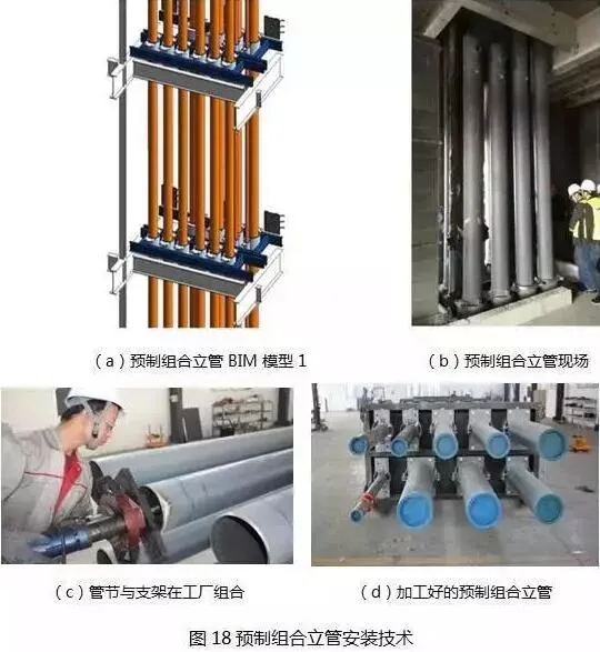
BIM application in this project follows three core principles: integrated design and construction, factory-based prefabrication with onsite assembly, and streamlined centralized-decentralized workflows. For example, the prefabricated composite riser installation technology combines fire water and condensate risers in the factory. Stable pipe sections covering 2-3 floors are prefabricated, cut, rust-proofed, and then installed onsite in one lift. Figure 18 shows this technology, which saves 40-45% in labor, 30-35% in machinery costs, and 8-10% in materials, while reducing onsite welding-related leakage risks.
Accurate construction reservations and embedding are ensured by integrating all models and coordinating reserved spaces. This guarantees building functionality and aesthetics in MEP and decoration design. Verification through integration reduces demolition, saves materials, and lowers labor. Figure 19 highlights collision detection eliminating conflicts between MEP components and structures before steel and concrete construction. Figure 20 shows statistics on comprehensive coordination and problem resolution in underground zones B006-B003. Coordination is an ongoing, multi-stage process, with collision issues steadily decreasing.
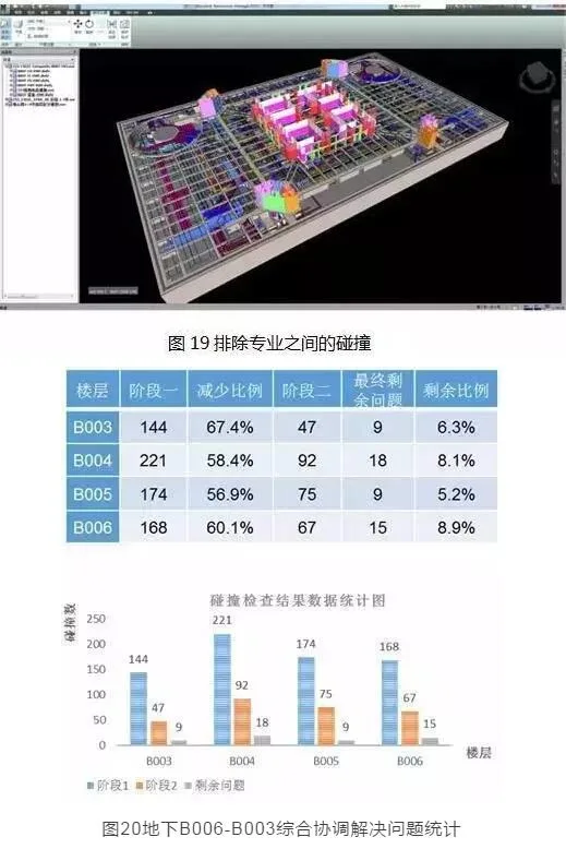
Figure 20: Statistics of Comprehensive Coordination and Problem Solving for Underground B006-B003
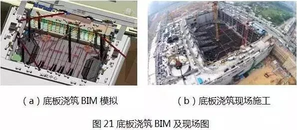
During construction, BIM simulation primarily guides onsite work rather than serve as visualization. For instance, during the bottom slab pour of 56,000 m³, the surrounding road pipe galleries were complete, with only Guanghua Road available for transport. BIM was used to optimize construction layout and simulate the entire pour process. The “string pipe and chute” method was adopted with government approval. BIM also supported onsite coordination, enabling a record-setting continuous pour in China (Figure 21).
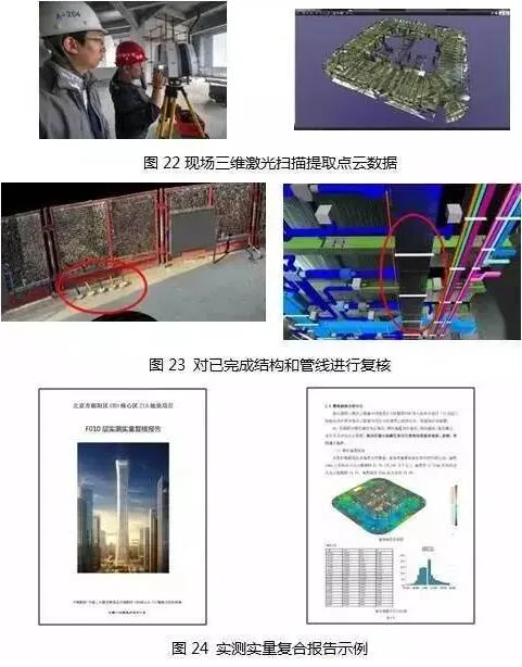
BIM coordination can identify many issues, but onsite construction inevitably has deviations. To address this, 3D laser scanning captures point cloud data (Figure 22), enabling design review of completed structures and pipelines (Figure 23). This ensures construction accuracy, helps integrate unbuilt systems into existing models, and addresses issues like ceiling deviations during MEP installation. Comparing point clouds with BIM models generates automatic error analysis reports (Figure 24), highlighting quality control weaknesses. Repeated problems across floors require serious attention. Collision detection using point cloud data is more realistic, preventing installation conflicts caused by onsite deviations. Figure 25 illustrates this process.
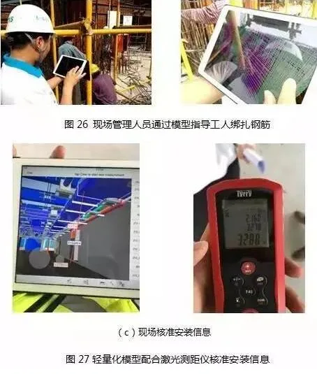
Using BIM lightweight models, onsite managers access models via mobile devices to guide rebar tying (Figure 26). Steel plate shear walls divide steel bars into halves, requiring close comparison with models. Laser rangefinders assist in verifying installation accuracy across disciplines (Figure 27).
3. Summary
By the end of 2016, the project completed 806 detailed design drawings and model approvals: 358 for steel structures, 227 for MEP, 145 for decoration, 37 for curtain walls, and 39 for other specialties including elevators and fire doors. There are 652 BIM models for comprehensive design, totaling over 700GB for process models. The latest overall building model weighs 35.4GB. The project’s Revit family library contains over 300 component families tailored to specialties like MEP, fine decoration, curtain walls, elevators, and window cleaning machines. Nineteen rounds of comprehensive model coordination resolved over 5,600 issues, including 900+ interdisciplinary conflicts, significantly enhancing detailed design quality.
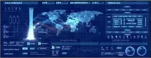
Figure 28 shows a preliminary intelligent operations platform (courtesy of Beijing Aibo Jiesi). With a complete BIM model, a customized software platform integrates BIM with building data management, equipment tracking, and security systems. It digitizes all building and room archives for easy access, records equipment production, warranty, and maintenance statuses, and monitors operational status. Integrated access control, alarms, and video surveillance ensure building safety, achieving a fully visualized, intelligent management system.
Conclusion
Although BIM technology currently appears to face some challenges, when applied as a practical tool to solve engineering problems rather than just for visualization, its potential remains vast.
Some small and medium enterprises hesitate to adopt BIM due to investment concerns and limited personnel. Owners and contractors must recognize BIM’s value in improving building quality and gaining economic and social benefits through investment. Additionally, cross-disciplinary expertise is crucial. Viewing models with a narrow focus limits BIM’s benefits. Interdisciplinary understanding enables deeper problem detection and greater value creation in BIM applications.


Must log in before commenting!
Sign Up