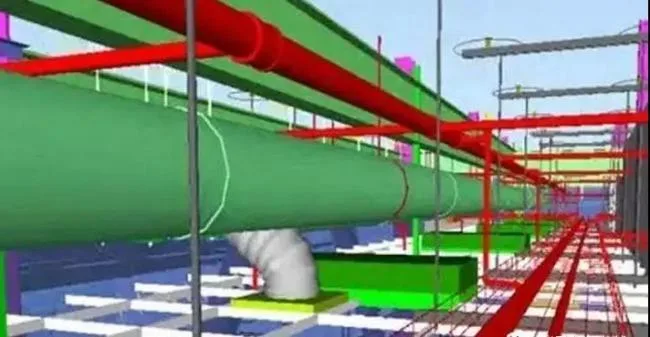
The key points for verifying the detailed design of electromechanical pipelines discussed here are derived from practical experience and comprehensive project summaries using BIM technology for pipeline deepening design.
1. Hole Reservation Verification
1. Are holes reserved for mechanical and electrical pipelines to pass through shear walls and floor slabs? (Including air ducts, vents, water pipes, cable trays, bus ducts, etc.)
2. Do the location and size of the reserved holes meet requirements? (Holes should avoid beams, columns, stairs, and must not impact building functionality. The hole size is generally larger than the pipeline diameter, especially for air outlets.)
3. Do holes in beams comply with specifications? (Ideally, pipelines should be located within the middle third of the beam’s depth, aligned with the beam’s centerline, and the distance from the hole to the beam’s top and bottom should be no less than one-third of the beam height.)
2. Pipe Well Verification
1. Is there a beam inside the pipe shaft? Generally, no beams exist inside pipe shafts, especially air shafts.
2. Do beams conflict with mechanical and electrical pipelines, particularly vertical pipes passing through beams?
3. Cable trays, bus ducts, and water pipes are installed along pipe well walls. Is the wall connected to the beam edge properly to prevent pipeline avoidance of beam bending?
3. Net Height Verification
1. Do ramps and equipment transport channels meet clearance height requirements?
2. Does the dense pipeline arrangement satisfy net height criteria?
3. Are large pipeline passage areas compliant with net height requirements?
4. Does the gravity drainage pipeline maintain proper net height clearance?
5. Can mechanical and electrical pipelines pass through stairwells while meeting clearance requirements? (Passing through stairwells is not allowed.)
4. Fire-Resistant Roller Shutter Inspection
1. Does the clearance under beams and column caps meet the installation height for rolling shutters (including space for the shutter and its box)?
2. Is there adequate space between beams and roller shutters for pipeline installation?
3. Does the height of the fireproof rolling shutter meet net height requirements?
4. Are mechanical and electrical pipelines designed within the roller shutter area?
5. Door Height Verification
1. Do door heights exceed floor heights, or is the clearance under sloped areas insufficient? (Common below mezzanines and ramps.)
2. Do elevator door heights exceed floor heights, or is the elevator door opening clearance insufficient? (Common in intermediate floors.)
3. Does clearance under beams and column caps meet door installation height requirements?
4. Is space between beams and doors sufficient for pipeline installation?
6. Air Shaft Suspension Plate and Double-Layer Plate Inspection
1. Does the reserved hanging board space meet air duct size requirements?
2. Does the reserved space for the double-layer plate accommodate the air duct size?
3. Does the pipeline layout beneath the double-layer plate meet net height standards?
4. Are holes provided in hanging plates and double-layer plates for air duct passage?
5. Are HVAC, structural, and architectural drawings labeled clearly and consistent?
7. Air Conditioning Unit Hanging Plate
1. Is the placement of the air conditioning unit’s hanging plate reasonable?
2. Are holes reserved for mechanical and electrical pipelines to pass through the AC unit hanging plate?
8. Water Pipe Systems
1. Is the pipeline system complete and correctly annotated? (Includes sprinklers, fire hydrants, domestic water, rainwater, drainage, etc.)
2. Are floor plans and system diagrams aligned? Do pipeline numbers correspond?
3. Is the pipeline layout logical? (Pipelines should not run parallel to overhead bridges, through air shafts, or enter electrical rooms such as distribution rooms, control rooms, or elevator machine rooms.)
4. When pipelines bend, try to route them upwards to avoid water and sediment accumulation. Even with drain valves, discharge points can be problematic if downward bends occur.
5. When arranging HVAC water pipes below beams, insulation thickness must be accounted for.
9. Air Duct Systems
1. Is the system complete and properly labeled? (Includes supply, return, exhaust, fresh air, smoke control, kitchen oil fume, and reserved ducts.)
2. Are floor plans and system diagrams aligned with corresponding system numbers?
3. Check air outlet positions—whether downward or side feeding—and ensure outlets are not obstructed.
4. Air ducts in high and low voltage distribution rooms should not be located directly above electrical equipment like distribution cabinets.
5. Does the fan room plan match detailed drawings?
6. Air duct designs often require flattening to accommodate limited net height. Typical air velocities: main air ducts at 6-8 m/s, smoke exhaust ducts at 15 m/s, and smoke exhaust supply air within 10 m/s. The width-to-height ratio should not exceed 4.
10. Cable Tray Systems
1. Is the system complete and accurately labeled? (Includes strong current trays, fire protection trays, communication trays, bus ducts, etc.)
2. Cable trays should bend at 45° angles wherever possible.
3. Avoid bending bus ducts as elbows must be custom-made and costly.
4. To prevent electromagnetic interference, strong current cable trays must not enter weak current rooms.
5. For multiple cable tray layers, maintain at least 250mm clearance between upper and lower trays.
6. When sharing support frames, keep at least 300mm between strong and weak cable trays, and maintain 50-100mm spacing between trays of the same type.
11. Other Considerations
1. Are mechanical and electrical pipelines reasonably routed through overhead, cantilevered, or crossing layers?
2. Do pipelines avoid passing through glass canopies, skylights, courtyards, or other viewing/lighting areas?
3. Are vertical pipes installed along walls or columns as required?
4. Is maintenance space reserved in areas with dense pipeline arrangements, such as rear passages?
BIM Architecture: Drainage, Mechanical and Electrical Pipeline Crossing, and Layout Avoidance Principles
1. Pipeline Crossing Treatment Principles
1. If drainage pipelines intersect with other pipelines, the treatment method must be approved by the property owner and relevant parties.
2. Pipeline crossing should maintain minimum clearance distances, allowing pressure pipelines to avoid non-pressure pipes and branch pipes, and smaller diameter pipes to avoid larger diameter pipes.
3. Pipeline crossing treatment methods:
– Concrete or reinforced concrete drainage circular pipes should be placed at the bottom, with cast iron and steel pipes on top. When upper pipelines are built first, brick supports are used for the lower drainage pipes.
– For drainage circular pipes under 600mm diameter, concrete pipes are placed below and cast iron/steel pipes above. If elevation conflicts occur, replace the lower drainage pipe with double-row cast iron pipes, reinforced pipes, or square ditches.
– When mixed structures or reinforced concrete rectangular channels intersect with steel or cast iron pipes above, and clearance is 70mm or more, brick piers support the pipe. If less than 70mm, low-strength cement mortar or fine aggregate concrete fills the gap without exceeding load capacity, and support angles must be at least 90°.
– Circular or rectangular drainage pipes can be installed on top with cast iron or steel pipes below, adding sleeves or pipe galleries when constructed simultaneously.
– If excavation is difficult due to deep burial, foundations for upper drainage pipes should be strengthened at crossing points.
– When drainage pipelines cross cable conduit blocks, backfill below the cable conduit foundation with low-strength concrete, lime soil, or bricks, ensuring no gaps and proper sand layering when constructed simultaneously.
– When both upper and lower drainage pipelines or heat pipe trenches are built simultaneously, strengthen the lower drainage pipeline and fill trenches with bricks or C8 concrete or sand.
– If elevation conflicts require the drainage ditch top plate to be flattened, ensure water discharge sections are not reduced.
– For prestressed concrete pipes passing below thermal pipe trenches, steel or reinforced concrete sleeves should be used first.
– When prestressed concrete pipes are above other pipes, support piers are built at the trench bottom or square ditch cover plate.
2. Comprehensive Pipeline Layout Planning in Mechanical and Electrical Installation Engineering
1. Purpose of comprehensive layout planning:
Optimize pipeline and equipment arrangements to create an orderly, rational, and aesthetically pleasing overall layout, maximizing building space utilization while reducing costs and increasing efficiency.
This planning stage is crucial for ensuring mechanical and electrical installation quality, especially in complex, intelligent buildings with multiple subsystems interconnected by pipes and cables. Given limited internal building space, rational layout is essential.
2. Planning, coordination, and implementation:
The general contractor must complete pipeline, electrical circuit, and mechanical equipment layouts for each system before starting mechanical and electrical work. Coordination with civil engineering is vital to reserve and embed necessary infrastructure during structural construction. This avoids later structural modifications and ensures sufficient space for both civil and mechanical details.


Must log in before commenting!
Sign Up