In mechanical and electrical installations, different pipeline systems are distinguished using a color-coding method, where each pipeline is painted in a specific color. Some facilities find painting entire pipelines cumbersome and prefer to apply just a single color ring at the valve or at the pipeline’s start, known as a color ring.
When there are multiple pipeline systems, the system name is often written on the color ring for easy identification at a glance. A simpler alternative involves using colored tape wrapped around the pipeline to indicate its function.
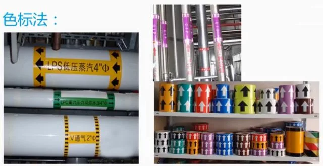
Comprehensive Management Color Marking
What does it mean when two or three tape rings are wrapped around a pipeline? In some projects, this indicates the system is divided into zones such as B zone, C zone, bottom zone, or high zone, based on different partitions. However, this tape method is prone to weathering and is unsuitable for pipelines carrying cold or hot media.
So, which colors should be used for different pipeline types? It’s important for everyone to agree on a color scheme so that the system can be quickly identified by color alone, without needing to read text labels. Below is the domestic standard for color coding, which should be followed as closely as possible.
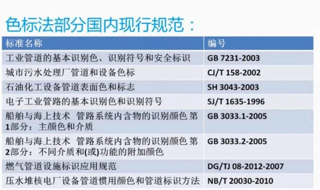
Partial Specifications of the Color Code Method
However, some clients have their own preferences and specify custom colors for their pipeline systems. In such cases, it’s essential to communicate with them and obtain their color standards to ensure consistency. This way, you won’t have to worry about which color corresponds to each system.
For BIM professionals, how can these color codes be integrated into their models? The images below show examples—one overall view and one close-up—where pipeline colors are distinct and system names are labeled, making the model vibrant and easy to understand.

Overall Pipeline View
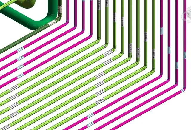
Partial Pipeline View
First, prepare some textures, like the gas texture shown below. This involves creating a simple label with the system name in black text on a white background. These textures should be saved in PNG format with transparent backgrounds to be effective. If you have advanced Photoshop skills, you can also add directional arrows to indicate the flow inside the pipeline.

Textures for Various Systems
Next, in the Project Browser, locate the pipeline system you want to modify and double-click it. For example, for a gas pipeline, a dialog box will appear. Navigate to Material > Appearance > General > Image, and add the prepared texture image.
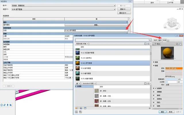
Steps to Set Up Material Textures
Finally, adjust the texture’s scale and repetition to achieve a balanced appearance relative to the pipeline’s thickness. The texture should tile seamlessly both horizontally and vertically, as illustrated below. Once finished, click “Finish” to apply the changes and see the effect.
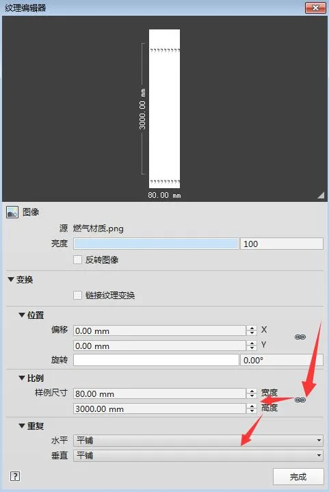
Texture Settings
However, after exporting to Navisworks (NW), some materials displayed using this method may not render perfectly. Do you have any suggestions for better ways to mark system names on pipelines?


This is good, you can distinguish it at a glance