BIM World
A Professional BIM Learning Platform


How to Model Cast-In-Place Concrete Box Girders Using Revit and Other Software

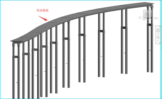
1. Begin by setting up the contour of the cast-in-place box girder and the bridge route design line using CAD.

How to use Revit to create cast-in-place concrete box girders? What software is used for modeling box girders

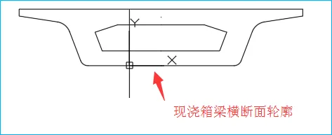
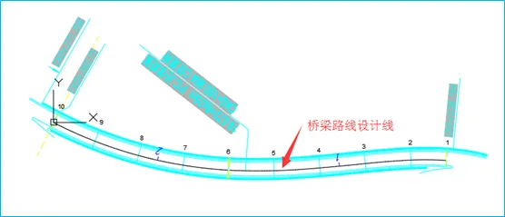
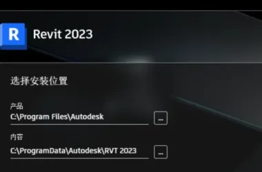
2. Open Revit and create a new family by selecting the metric structural foundation family template. Then, import the CAD drawings of the box girder profile and bridge alignment design lines into Revit.

How to use Revit to create cast-in-place concrete box girders? What software is used for modeling box girders

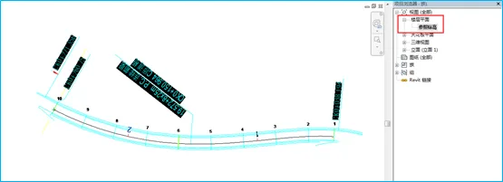
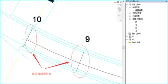
3. Switch to the reference elevation plan view. Copy the imported box girder cross-sectional view to both ends of the bridge route design line between Pier 9 and Pier 10. Rotate the cross-section so that it is perpendicular to the bridge route design line.

How to use Revit to create cast-in-place concrete box girders? What software is used for modeling box girders

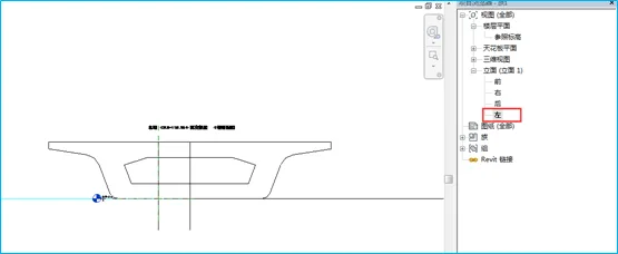
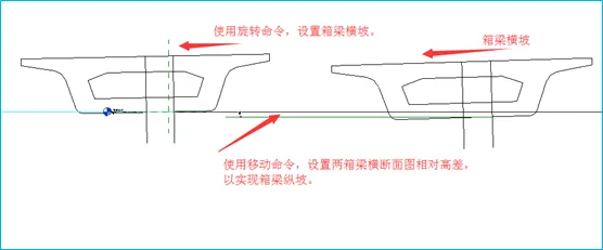
4. Switch to the left elevation view. Use the Move command to set the relative height difference between the two box girder contours, establishing the longitudinal slope of the box girder. Then, use the Rotate command to adjust the box girder’s cross slope.

How to use Revit to create cast-in-place concrete box girders? What software is used for modeling box girders

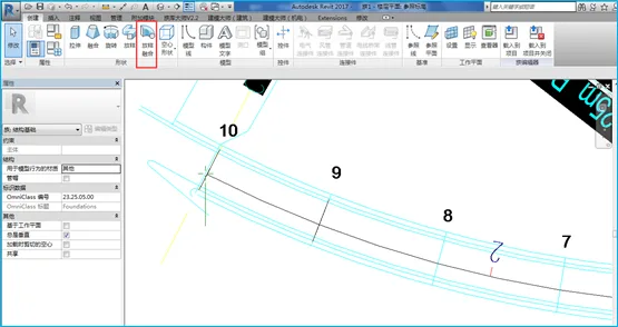
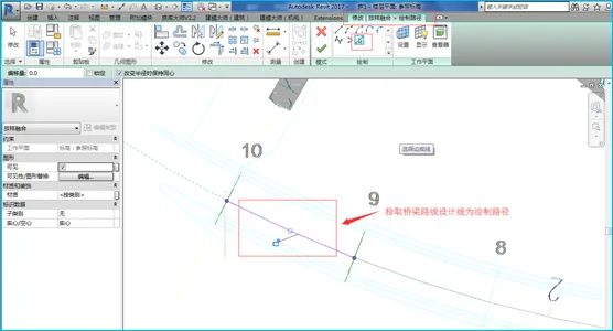
5. Return to the reference elevation plan view, select the Layout Fusion command, and pick the bridge route design line between Piers 9 and 10 as the path for drawing.

How to use Revit to create cast-in-place concrete box girders? What software is used for modeling box girders

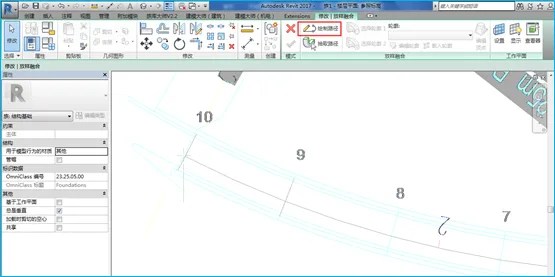
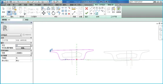
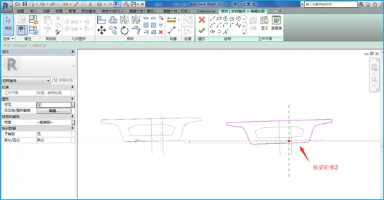
6. Select both contour 1 and contour 2, then click OK to complete the concrete box girder structural model.

How to use Revit to create cast-in-place concrete box girders? What software is used for modeling box girders

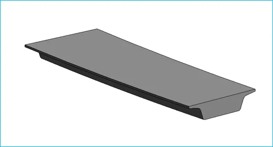
7. Using the same method, select the Hollow Layout Fusion command to create a hollow chamber inside the box girder.

8. Add materials, type names, and other relevant parameters to the box girder, then save your work.

9. Repeat the same process to create cast-in-place box girders between other bridge piers. Be sure to adjust parameters such as cross slope and elevation difference according to the specific design drawings for each span.

How to use Revit to create cast-in-place concrete box girders? What software is used for modeling box girders

xuebim
Follow the latest BIM developments in the architecture industry, explore innovative building technologies, and discover cutting-edge industry insights.
← Scan with WeChat
Like(0) 打赏
BIM WORLD » How to Model Cast-In-Place Concrete Box Girders Using Revit and Other Software

Comment Get first!

Must log in before commenting!


BIM World, A Professional BIM Learning Platform

Stay updated on the latest architecture trends and share new building technologies.

Contact UsAbout Us

觉得文章有用就打赏一下小编吧

非常感谢你的打赏,我们将继续提供更多优质内容,让我们一起创建更加美好的网络世界!

支付宝扫一扫

微信扫一扫

Account Login

By signing in, you agree toUser Agreement

Sign Up