— When dimensioning water pipes or air ducts in section views, typically only the centerline position of the pipe can be marked, while the pipe boundaries cannot be indicated. This limitation often causes inconvenience.
— However, by using the “Can be done/graphic” feature in the “Elevating and lowering” command, it is possible to achieve the result shown in the image below, allowing direct annotation of the pipe boundaries.
Below are the detailed steps and explanations:
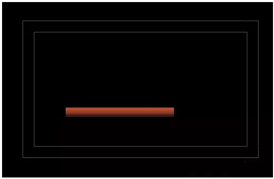
1. Draw a pipeline using the electromechanical template.
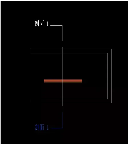
2. Create a section in the plan view and enter the section view.
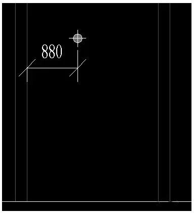
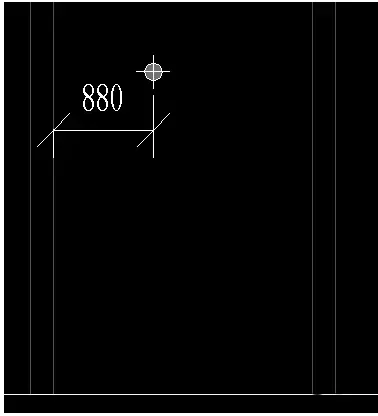
3. Attempt dimension annotation in the section view. Notice that only the centerline of the pipeline is selectable.
4. Open the “Can be done/graphic” dialog box and observe that all commands within the pipeline (or cable tray) “Rise and fall” options are enabled.
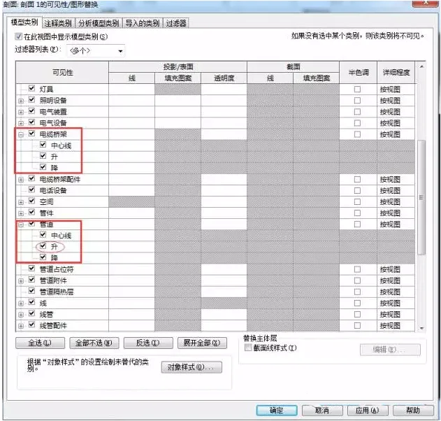
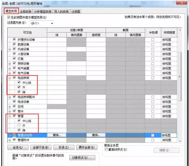
5. Under the pipeline commands, uncheck the “Upgrade” option.
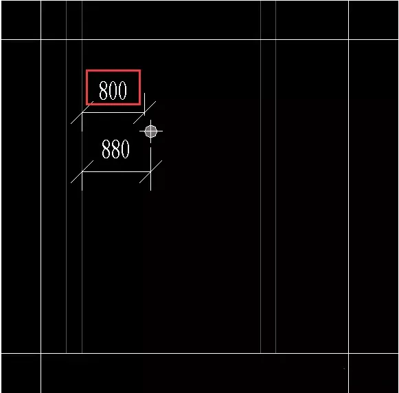
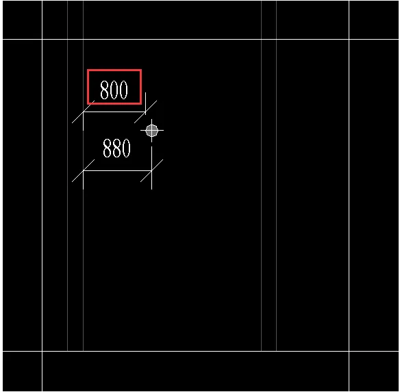
6. Return to the section view and press the Tab key again to select the annotation position. You will find that you can now annotate the pipe boundary directly.
Regarding the settings under “Mechanical Settings” — specifically “Pipe fitting annotation size” and “Pipeline elevation/lowering annotation size” — their meanings are explained below:
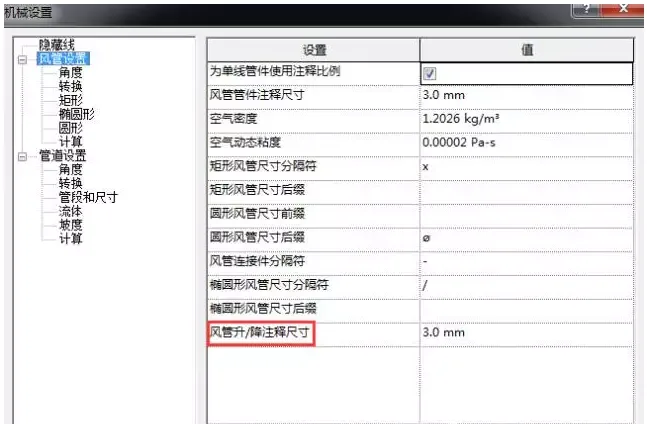
Fitting annotation size: Defines the print size of fittings and attachments drawn in a single line view. This dimension remains constant regardless of the drawing scale.
Pipeline elevation/descent annotation size: Specifies the print size of elevation or descent annotations drawn in a single line view. This size also remains unchanged regardless of the drawing scale.


Must log in before commenting!
Sign Up