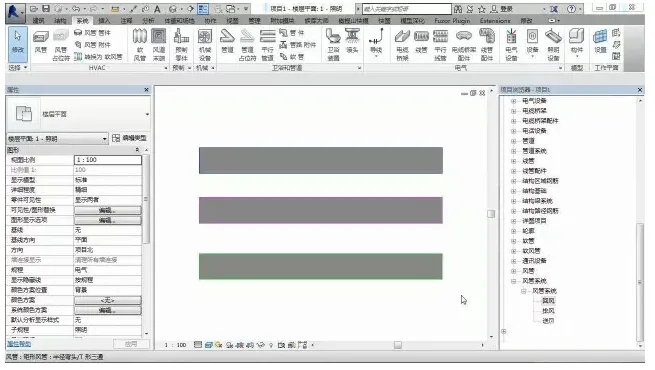
Revit’s default duct systems include three types: return air, exhaust air, and supply air. However, in practice, you may also need to work with systems like smoke exhaust. Below, we’ll guide you through the steps to create a smoke exhaust system within an air conditioning setup.
Step 1: Open Revit. By default, the duct system options show only return air, exhaust air, and supply air, as illustrated below:
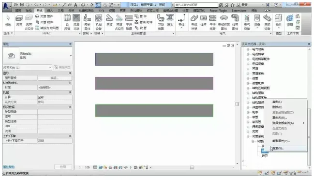
Step 2: Since the smoke exhaust system is similar to the exhaust system, you can duplicate the exhaust system and rename it. To do this: right-click on the exhaust system, select Copy, then choose Exhaust system 2. Rename this to Smoke Exhaust.
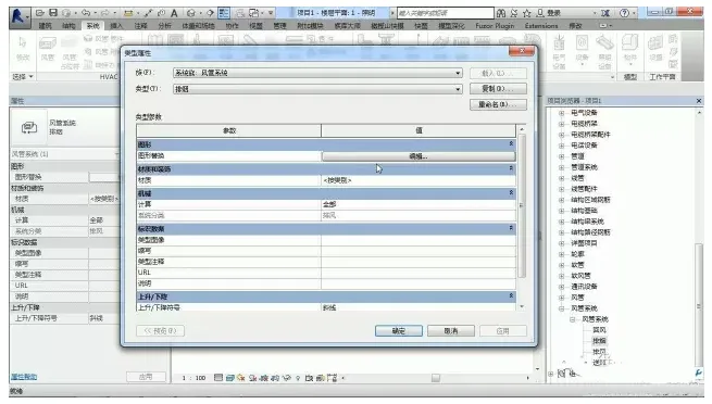
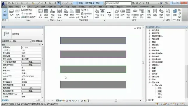
Step 3: Double-click on the newly created smoke exhaust system to open its properties. Here, you can modify parameters such as graphic overrides, including color changes. Once you’ve made the adjustments, click OK to confirm.
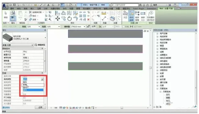
Step 4: You have now created a basic smoke exhaust system. To start drawing the air ducts, select the duct tool. In the system type dropdown, you will see the smoke exhaust system available. Select it to proceed with your drawing.
Step 5: After completing your drawing, verify that the parameters within the system match your requirements.


Must log in before commenting!
Sign Up