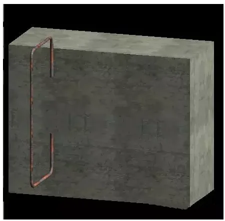
The most common method for placing steel bars in a structure is to position them on a single plane, as illustrated in the images below:
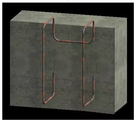
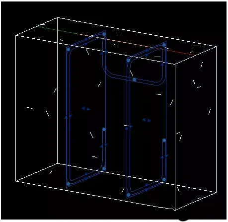
However, sometimes it is necessary to place steel bars across multiple planes to achieve more complex results, as shown in the following images:
By adjusting the positions of the steel bars accordingly, you can achieve the desired configuration, as demonstrated below:
![]()
The solution to these scenarios is achieved through the “Multi Plane” command.
To use this feature, you must first select the steel bars that have already been drawn on a plane and then edit their sketches to enable the multi-plane display.
Below are the detailed steps and analysis for utilizing the “Multi Plane” command:
Steps:
1. Create a structural model—using a rectangular beam as an example—and place steel bars on one of its faces.
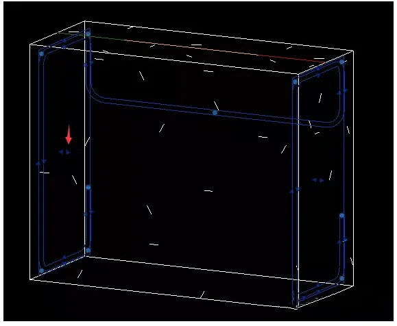
2. Switch to a 3D view to display the steel bars clearly.
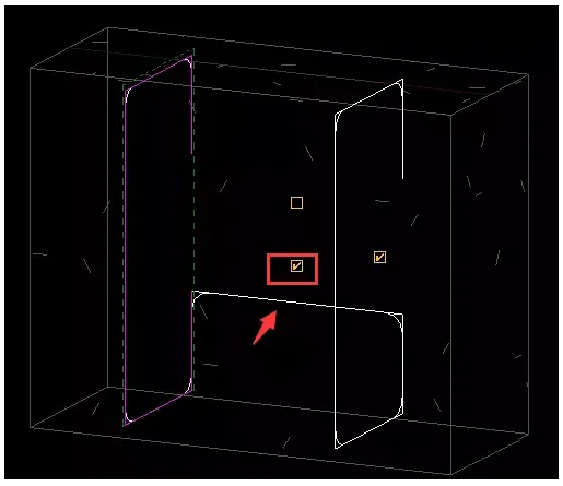
3. Select the steel bar, click the Edit Sketch command in the modification panel, and check the Multi Plane option under the steel bar panel.
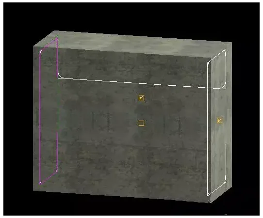
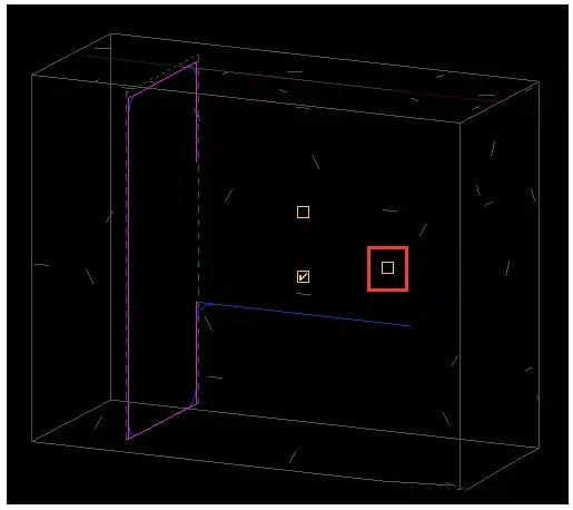
4. Refine the shape of the multi-plane steel bars by adjusting the three checkboxes available.
5. Once you have finalized the shape of the steel bar, click to complete the editing.
6. Select the steel bar and use the control handle to adjust its position, achieving the effect shown at the beginning.
Analysis of the “Multi Plane” command:
This command works best when viewed in 3D, offering three checkboxes to further customize the shape of multi-plane steel bars. Hovering over each checkbox will display a tooltip explaining its function.
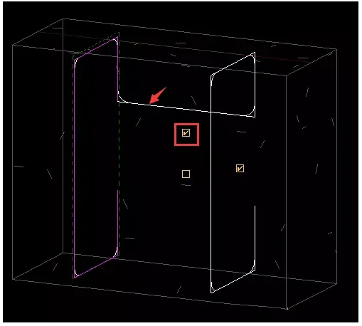
First checkbox: Enable/Disable the first connector segment
This toggles the position of the connector segment. When enabled, the first line segment is used; when disabled, the second line segment is applied (as shown in Step 4).
Second checkbox: Disable copying of shape segments
Disables the duplication of shape segments but retains the connector segments at their locations.


Must log in before commenting!
Sign Up