To begin, open your project file and switch to the plan view. Then, click on the “View” tab. From the dropdown menu in the “3D View” panel, select “Roaming” by pressing the corresponding button (see Figure 1) to enter the roaming path drawing mode.
Next, choose “Self” in the drawing slow board volume. Set the offset to 1750 (this offset refers to the visual height of the roaming camera) as shown in Figure 2. Now, draw the roaming path around the building. Once finished, click the “Complete Roaming” button (see Figure 3).
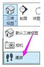
Figure 1
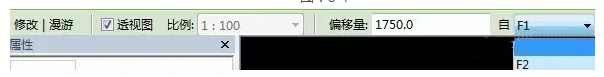
Figure 2
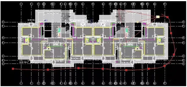
Figure 3
At this stage, the view will automatically switch to the “Modify | Camera” interface. Click on “Edit Roaming” to enter the roaming editing mode. In the control options, you will find four commands:
- Activity Camera
- Path
- Add Keyframe
- Delete Keyframe
For now, select the “Activity Camera” command (see Figure 4). Then, click on the solid origin point in the path view window to adjust the viewing direction of the roaming path. You can also click and drag the hollow origin point to change the depth of view in the roaming window (see Figure 5).
If you switch to the “Path” command, you can modify the roaming path itself.
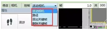
Figure 4
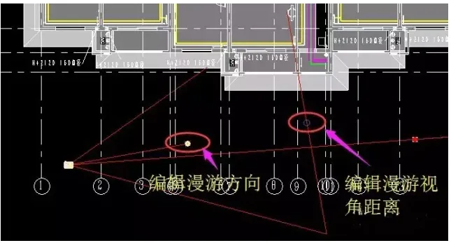
Figure 5
To view your roaming path, locate the “Roaming” section in the Project Browser. Double-click on the walkthrough you created (see Figure 6) to enter the walkthrough view. Then, click the “Play” button (see Figure 7) to start the roaming animation along your drawn path.
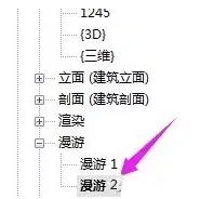
Figure 6
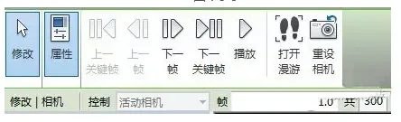
Figure 7
Additionally, you can export the roaming path you created by navigating to “Export” → “Graphics and Animations” → “Roaming”, choosing the desired export format.


Must log in before commenting!
Sign Up