Nesting Comprehensive Practice of Adaptive and Panel Fill Pattern Families – Times Square Red Heart Design
Analysis:
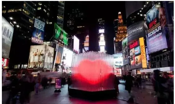
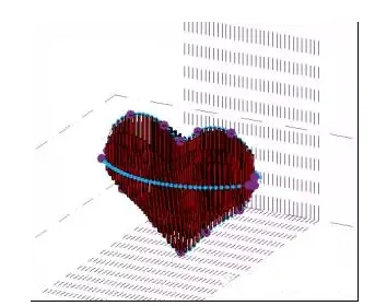
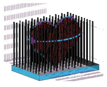
The Times Square Red Heart Design consists of a series of glass pillars illuminated by neon lights, forming a three-dimensional glowing red heart. This effect is achieved using an adaptive volume family combined with a curtain wall metric panel fill pattern family.
Here is a brief overview of the process:
1. Create a metric volume and use reference points and reference splines to outline the heart shape.
2. Draw two semicircles using reference points and lines, then divide these four lines with the intersection command.
3. Create an adaptive conventional model by drawing four reference points, generating a solid sheet shape, and editing it accordingly.
4. Develop a new fill pattern family based on the curtain wall metric panel, design a cylindrical neon tube, then load it into the adaptive family, placing it in order at the reference points.
5. Use reference lines to sketch a square within the volume and mark its base.
Detailed steps and command explanations:
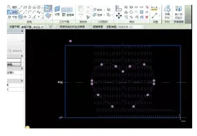
First, create a metric volume. Switch the view to the north elevation, select the vertical work plane, and copy it 16 units to the left and right respectively.
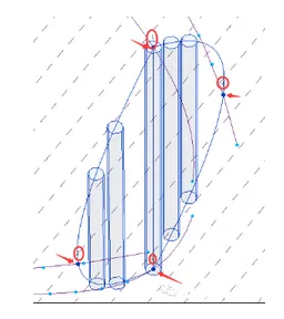
Using reference points and reference splines, draw the heart shape. Since the heart has a three-dimensional appearance, add two semicircles using reference lines.
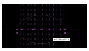
Next, divide these four lines separately (first change the number of divisions to 2), then use the intersection point option to select the previously drawn horizontal reference plane.
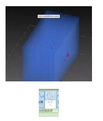
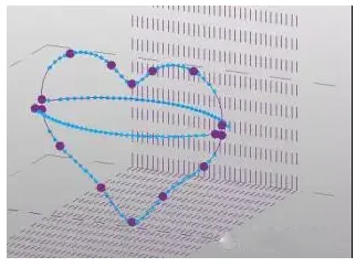
This results in 33 reference points on each side, which helps position the neon tubes accurately. Then, create an adaptive conventional model by randomly drawing four reference points and using three points plus one line to form a circle from left to right.
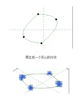
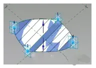
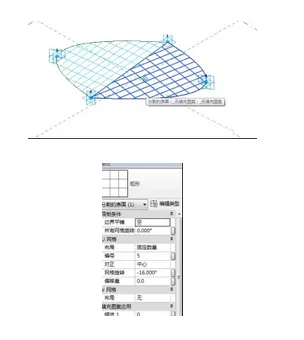
Draw a reference line from point 3 to point 1, create solid sheets individually, divide the surface, and edit the grid through the attribute bar.
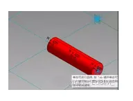
Create a new curtain wall-based metric panel fill pattern family. Locate the reference points and draw on the reference line. Use the reference point as the center to draw a circle with a radius of 400 using a reference circle. Then select the circle and reference line to model a cylindrical neon tube.
Load this into the adaptive family, select the mesh, and switch to the family in the properties bar.
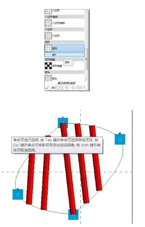
Then, load it into the metric volume model and place it at points 1, 2, 3, and 4.
Place the elements sequentially at each point.
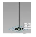
Next, use reference lines to draw a square within the volume and define its base. As in previous steps, divide it, then draw a vertical cylinder in adaptive mode to create a transparent light tube on its outer ring. Load this into the volume grid, select the grid, and change its family in the properties bar.
Finally, remember to adjust the material properties.
Significance of command selections in adaptive mode:
Select Control Curve: When enabled, the reference point acts as the driving point for one or more lines. Moving this point modifies the geometry. If disabled, the parameter becomes read-only, and the reference point no longer drives the geometry.
Choose to be controlled by the subject: When enabled, the reference point is host-based and moves with its host geometry. If disabled, the parameter becomes read-only, and the reference point is no longer linked to the host.


Must log in before commenting!
Sign Up