1. Project Introduction
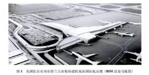
The existing Menard Airport in Atlanta, Georgia, USA, was originally constructed for the 1996 Atlanta Olympics and has since served for nearly two decades. Due to the rapid growth of international flights operated by Delta Air Lines, which has far exceeded the capacity of the current facilities, the Atlanta city government has approved the construction of a new 115,000-ton terminal on the east side of the existing airport. This new terminal is designed to simultaneously accommodate 12 wide-body international aircraft and 16 domestic aircraft.
In addition to the terminal building, the project includes a new passenger rapid transit system connector, a parking facility with 1,100 spaces, and improvements to Menard Jackson Avenue along with a new long-term parking lot surrounding the airport (see Figure 1).
Although fundraising for the new international terminal began in the 1990s, the project was temporarily delayed due to financial constraints. In the summer of 2007, the Atlanta city government commissioned a consortium of four construction companies, HMMH, to restart the project with a targeted completion date by the end of 2011.
The centerpiece of the project is a five-story cast-in-place concrete terminal building (shown in Figure 2). The floors are organized as follows:
- 1st floor: Automated ground transportation system for passenger luggage, airport-dedicated lines, and office systems.
- 2nd floor: International arrivals area, including customs and immigration facilities.
- 3rd floor: Main floor, primarily for internal luggage transfer and connection to the aircraft apron.
- 4th floor: Passenger departure, ticketing, and check-in areas.
- 5th floor: Reserved for VIPs and administrative personnel.
The total project cost is $1.2 billion USD, funded through a combination of airport construction fees ($7.5 per passenger), airport-issued bonds, and federal government contributions.
2. Application of BIM Technology
2.1 Software Used in the Project
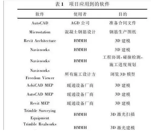
Although contract requirements only specified the provision of 2D design drawings, HMMH opted to implement 3D BIM technology and mandated all subcontractors and related construction parties to use 3D models throughout the project.
HMMH primarily utilized Revit as their main BIM modeling software and extensively applied Navisworks for construction coordination, clash detection, and 4D scheduling. Table 1 provides a detailed list of software tools employed on the project.
2.2 Project Design and Construction Progress
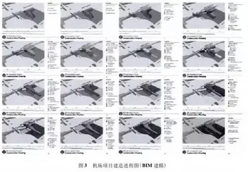
In November 2007, a simple conceptual 3D model with color coding was developed to illustrate the overall construction plan (see Figure 3). By May 2008, HMMH commenced the first phase of 3D modeling to build the BIM model for the new terminal. Modeling engineers created their 3D designs primarily based on 2D drawings supplied by the design team.
In autumn 2008, the team acquired 3D laser scanning equipment to capture the existing baggage handling systems. These scans produced 3D point clouds, which were then converted into detailed 3D models (shown in Figure 4). The scanning and modeling process was completed by 2009, alongside the final terminal building model and animated construction progress visualizations.
2.3 Project Coordination
By leveraging BIM technology, HMMH significantly enhanced coordination across multiple disciplines involved in the terminal’s construction. These included architecture, concrete and steel structural work, mechanical, electrical, plumbing, fire protection, specialized equipment, and baggage handling systems.
The weekly workflow was structured as follows:
- Thursday: HVAC equipment coordination meeting.
- Friday and Monday: Dedicated modeling days.
- Tuesday morning: HMMH and all subcontractors upload their latest files to the FTP site.
HMMH then merges all files and runs clash detection using Navisworks. After verifying the results, a coordination log is generated and discussed during the construction site coordination meeting the next day (Wednesday). Key personnel from HMMH and subcontractors participate in these meetings.
Conflicts are evaluated based on their impact on the construction schedule and costs. Unresolved or new issues are assigned to respective teams for resolution and revisited at the following Wednesday’s coordination meeting. This cycle repeats continuously throughout the construction phase.
Additionally, HMMH developed a 3D visualization tool called “FieldBIM Views” to assist in project progress coordination. This tool enables easy printing of required 3D views, with metadata such as creation time, model creator, and descriptions clearly marked (see Figure 5), facilitating effective sharing of BIM model information across the team.
3. Reflections on BIM Application
While BIM offered significant advantages to this project, it also presented some challenges. One major issue was the large file sizes generated by detailed models. For instance, the steel structure subcontractor’s detailed 3D model of steel connections reached 8GB, which was too large for Navisworks to process efficiently. To address this, the subcontractor divided the original model into smaller sections based on the construction sequence.
Other challenges included higher labor costs and time investment during the early stages of 3D modeling, especially when designs underwent frequent changes. Moreover, the on-site construction team was initially unfamiliar with BIM technology, requiring HMMH to provide specialized training to improve BIM proficiency among construction personnel.
Despite these drawbacks, the benefits brought by BIM far outweighed the challenges. The use of advanced modeling techniques like 3D laser scanning, more sophisticated scheduling tools, and BIM visualization greatly enhanced construction design coordination. These improvements are expected to strengthen HMMH’s construction management capabilities in future projects.


Must log in before commenting!
Sign Up