1 Singapore Sports Centre
The Singapore Sports Centre is a green, eco-friendly, and energy-efficient facility designed specifically for tropical climates, utilizing BIM technology throughout its development. Serving as both an international competition venue and a large commercial entertainment center, it accommodates up to 55,000 spectators and operates year-round without interruption. The design concept integrates multiple sports facilities on a unified platform, including a sports stadium, a multi-purpose sports center, an indoor swimming pool, and a water entertainment center. Completed in 2014, the project features the world’s largest arched roof span, where optimizing steel usage and reducing structural weight were key design goals to achieve the architectural vision. Since Singapore has established BIM standards, the project strictly follows the country’s BIM design guidelines from conception through construction.
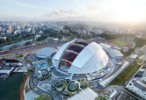
The project required extensive coordination across multiple individual buildings, necessitating a comprehensive construction management system. The most complex design element was the stadium’s opening roof, which, as the largest indoor sports stadium roof globally, presented challenges including lighting integration and technical issues related to roof movement. BIM technology offered several advantages, such as providing detailed construction models, facilitating multidisciplinary coordination, automatically generating accurate profiles, performing collision detection, and enabling virtual walkthroughs. Moreover, the building information model allowed for efficient access to data on building performance, thermal efficiency, and lifecycle analysis.
Notably, the Singapore Sports Centre is the largest sports stadium globally designed and built through a Public Private Partnership (PPP) model. Under this model, private sector partners are responsible for design and construction, often with fixed pricing, while meeting public sector specifications. For Arup, the architectural design firm, BIM use brought significant benefits. They employed Dassault Systèmes’ CATIA, Gerry Technologies’ Digital Project, and Microsoft Office 2007 throughout the design process.
The CATIA 3D model allowed architects to control data via Excel 2007, enabling rapid incorporation of structural feedback into existing models and accelerating updates that could be promptly shared with other design professionals. For repetitive building types, a design database was established, allowing reuse of site and seating data, thereby saving time and enhancing design accuracy. Furthermore, the combined use of CATIA and Digital Project enabled the curtain wall construction units to be determined early in the design phase, integrating curtain wall design into the overall building process. Later, the curtain wall manufacturer used Arup’s BIM model for fabrication, improving accuracy while reducing on-site labor and time.
2 Aviva Stadium
Located in Dublin, Ireland, the Aviva Stadium—also known as Lansdowne Road Arena—opened in 2010 and is Ireland’s only UEFA five-star football stadium. It serves as the home ground for the Irish national football team. Construction began in 2007 and was completed in 2010, with a seating capacity of 50,000. The stadium’s roof features a distinctive wave-like design.
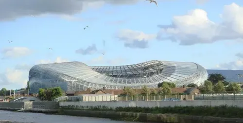
Due to the complex exterior design and the need for continuous adjustments within constrained conditions, the design team developed a collaborative workflow centered on a parametric model created with Bentley’s GC software. This parametric approach allows the stadium’s geometry to be controlled by parameters, eliminating the need for manual remodeling when the design changes.
Technical Implementation of Parameterization Method 1:
The team implemented peripheral 3D parametric models using parameter data, static geometry, and GC script files. Parameters correspond to surface control points extracted from an original Rhino model and stored in Excel spreadsheets. These numerical data are fed into GC via script code, enabling automatic updates if the Rhino model or data points change. A graphical interface based on control curves was developed to easily manipulate the overall model shape and refine the original design. The final stadium skin shape results from combining this control system with global constraints and resolving conflicts with the stadium’s core structure. The geometric definition starts with vertical plane arrays controlling the positions of third-layer structural roof elements, positioned at intersections of parameterized path curves and the stadium’s radial structural grid. Structural supports are defined between these planes, which serve as spatial references extracted and converted into 2D cross-sectional views.
2. Structural Analysis and Feedback
Throughout design development, the stadium enclosure model underwent frequent modifications, requiring an effective communication system for design intent. One major challenge was integrating engineering analysis into the parametric workflow. To address this, C# was used to extend GC’s internal functions through its API, creating a custom application that links parametric models with structural analysis software. This app automatically specifies cross-sectional dimensions for each structural element and can generate a comprehensive stadium roof structure model based on architectural guidelines and initial concepts, producing analysis data files without manual input.
3. Shell Detail Design
The stadium’s outer surface comprises a polycarbonate louver panel array that closely follows the shell’s curvature. The initial surface design was parameterized and generated along panel boundaries in GC. Panel widths remained constant, while lengths adjusted within manufacturer limits. Software automatically adapted each panel’s orientation and size to fit the shell’s curvature. Given the vast scale and component quantity, modeling the entire stadium shell parametrically was impractical. To solve this, the shell was divided into smaller sub-models aligned with structural supports on the third-level truss. This subdivision made managing the large parametric model feasible.
Post-Evaluation
The integration of custom parametric models with structural analysis significantly reduced time-consuming, error-prone manual modeling and revisions. The design-analysis feedback cycle was shortened, demonstrating the efficiency of this approach.
Architecturally, parametric modeling enabled detailed exploration and testing of all surface design options. Collaboration between architects and manufacturers optimized the high-value surface system for cost-effective production and installation.
3 Avia Stadium
Completed in 2010, the Avia Sports Stadium has a seating capacity of 50,000. Designed by Populous (formerly HOKSport), a leader in sports architecture, it was the first stadium fully designed using parametric methods. The design aims to create a local landmark while harmonizing with the surrounding environment.
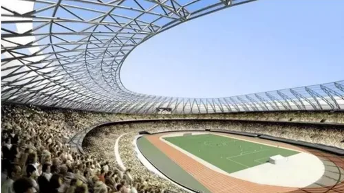
The Avia Stadium features a freeform curved design created with Bentley’s GC software, employing a multi-scheme comparison to minimize environmental impact. Transparent skin materials maximize natural light, helping the building blend with its surroundings. The design integrates the roof structure and building facade into a unified form that wraps around the main structure, breaking from the traditional separation of roof and facade in sports venues.
The design process begins with creating a 3D model in Rhino to quickly establish and evaluate the building’s shape and footprint. This model is then imported into GC to generate a script that produces a highly modifiable GC model. Structural engineers optimize this model with design data, allowing architects and engineers to collaborate on a shared parametric model.
Within this integrated model, architects focus on the building skin and form, while structural engineers adjust component sizes and positions. All parameter changes and model data are tracked in Excel, enabling seamless updates. The curtain wall consultant and architects used this unified model to analyze panel sizing issues, creating a detailed curtain wall node model in SolidWorks based on the original structural centerline. This allowed optimization of the curtain wall design, reducing the minimum polycarbonate panel thickness from 8 mm to 3 mm. This reduced roof material weight from 200 tons to 80 tons and cut material costs by 40%, saving approximately $3.5 million overall.
Additionally, the BIM model facilitated energy analysis, supporting sustainable design goals. For firms with clear task divisions, the parametric information model enhanced cross-company collaboration, accelerating design and coordination. Throughout the process, the architect led the design model development. The completed BIM contained comprehensive building data and enabled on-site adjustments of facade panel fabrication and positioning, significantly reducing labor and material costs during construction.


Must log in before commenting!
Sign Up