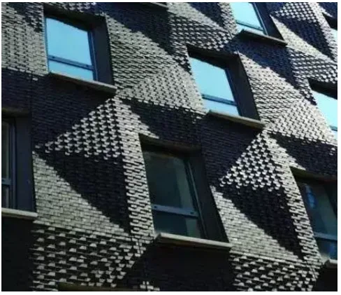
▲ Surface construction effect
Challenges in Façade Design
The 290 Mulberry Street project is situated on the northwest edge of Nolita, New York, bordered by Houston Street to the north and the historic Puck Building on Mulberry Street to the west. Each standard floor spans 2,000 square feet. Given the high real estate values in this neighborhood, optimizing the façade thickness is essential to balance the added value of its design with the saleable interior space.
Urban zoning mandates that the building’s exterior walls facing Houston and Mulberry Streets adopt a “stone building” aesthetic, harmonizing with the adjacent Puck Building, one of New York’s most renowned stone structures.
As a result, the building’s surroundings directly shape its exterior, reflecting the architect’s deliberate response to neighborhood context and regulatory requirements. SHoP’s design philosophy focuses on interpreting local laws and contemporary responses to the Puck Building, steering clear of mixed or inconsistent treatment of stone buildings and details.

▲ A corner of the Puck Building, with 290 Mulberry under construction in the background
Transforming Challenges into Opportunities
The design goals for 290 Mulberry Street focus on maximizing interior space, adhering to zoning projection limits, and minimizing the overall thickness of the façade. These constraints led to a modern reinterpretation of traditional brick detailing.
SHoP proposed a “ripple” design for the skin—where brick blocks protrude and stack across the façade, forming smooth, rounded corners rather than flat surfaces. However, this design conflicts with zoning expectations for the surrounding environment. The “canyon” effect of the ripple is located at the building’s setback line, and although the protrusion is only 0.75 inches (about 1.9 cm), nearly the entire façade extends beyond the allowable building line.
To address this, SHoP used advanced analysis software to calculate the average protrusion beyond the setback, ensuring compliance with building codes.
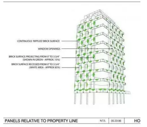
▲ Drawings illustrating the analysis of building skin regulations
Achieving precise measurements for each brick by manual masonry would be impractical. Instead, these bricks are prefabricated into custom panels in a factory setting.
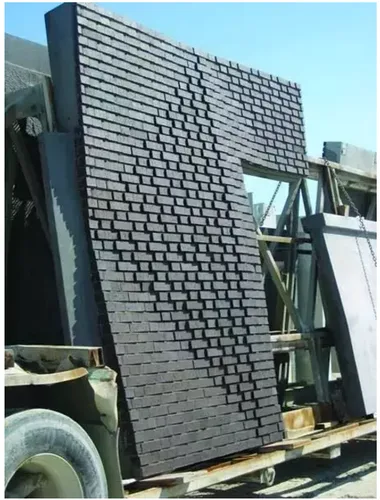
▲ Prefabricated brick panels before transportation to the construction site
From Concept to Construction
The design process operates on two scales simultaneously. On a small scale, individual bricks protruding from their neighbors cannot extend more than 0.75 inches (approximately 1.9 cm). On a larger scale, panel layouts must align precisely with the building’s column grid, floor heights, and window openings.
Through the use of both physical and digital design models, SHoP refines the project by iterating from detailed elements to the overall brick arrangement, and vice versa, ensuring the façade design integrates seamlessly with the building’s structure.
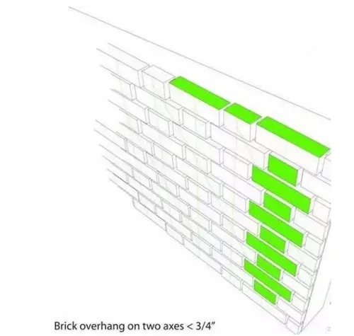
▲ Diagram illustrating the One Line One Line Masonry (Brick) method for the brick façade
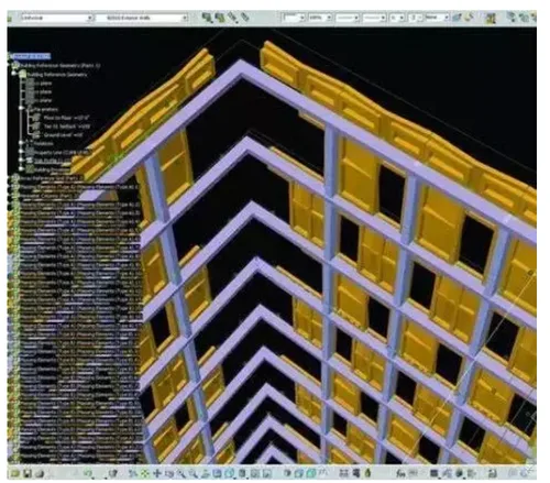
▲ Computer model showing the coordination between window placement, panel design, and building structure
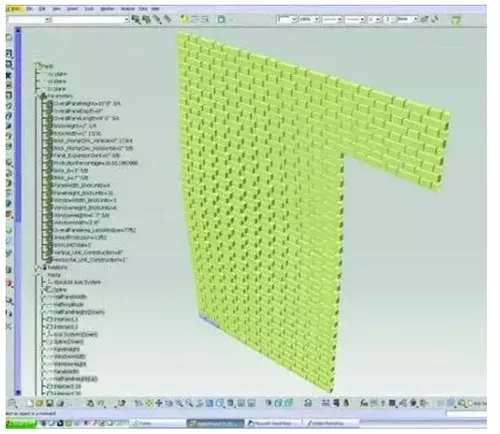
▲ Parameterized model controlling the layout of each brick via panel design
The architects view the building skin as a layered, evolving process rather than a fixed, preconceived form. Parametric digital modeling of the façade begins before finalizing the building’s shape, enabling exploration of component possibilities and manufacturing techniques within set parameters rather than fixed geometries.
This project marks SHoP’s first use of the Building Information Modeling (BIM) platform—a software technology that integrates detailed information about each component. BIM automatically updates all related views and components when any change is made to the model.
SHoP employs Revit, a BIM software, to parameterize and coordinate data from various tools, generating accurate drawings and files based on panel data created by other software.


Must log in before commenting!
Sign Up