The Kunming Yueman Xincheng project is situated in the Wujiatang area of Guandu District, Kunming City. This government-led resettlement housing initiative represents a large-scale livelihood development. Covering an area of 92,805.10 square meters, the site stretches approximately 307 meters from east to west and about 313 meters from north to south. On its eastern boundary lies Changhong West Road, with planned roads along the south and west sides.
The project is extensive, featuring a construction area of roughly 560,000 square meters. Construction involves twelve towers being built concurrently over a period of 540 days, demanding stringent construction organization and technical support. The installation scope includes HVAC smoke control systems, water supply and drainage, fire hydrant and sprinkler systems, as well as both strong and weak electrical systems. The first basement floor covers around 70,000 square meters, including five towers with civil air defense areas beneath them. The underground mechanical and electrical pipeline network is notably complex.
As the first project to apply BIM technology by the Hunan Construction South Bureau, the Group’s BIM Center customized a dedicated BIM workstation plan, drawing on prior project experience and the unique characteristics of this development.
Starting mid-March, members of the Group’s BIM Center and technical experts from the Southern Bureau formally initiated BIM technology work on this project. As the team’s foundational efforts progressed, specific BIM applications began to be implemented, focusing on both electromechanical and civil engineering aspects. Below, we share key technical points from these perspectives.
1. Mechanical and Electrical BIM Applications
Integrated Electromechanical Optimization
Inspection of Pipe Well Layout
We examined pipe well layouts to check for the presence of beams, cable trays, bus ducts, and water pipes. Typically, these components are installed along walls. If walls are not adjacent to beam edges, pipelines may bend or detour to avoid beams. This inspection focused particularly on vertical pipes passing through beams.
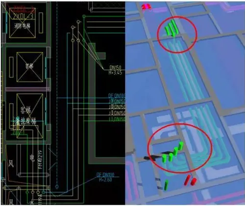
For example, the basement pipelines on the negative first floor of Tower 2 pass through beams. The basement podium has a floor height of 4 meters, while the tower includes a mezzanine above the two basement levels. Consequently, the negative first floor has a lowered slab of 600 mm, resulting in a floor height of 3.4 meters. The design drawings indicate a turning elevation of 3.45 meters to avoid beams, which conflicts with the top slab. This issue occurs in multiple tower areas and will not be further detailed here.
Net Height Verification
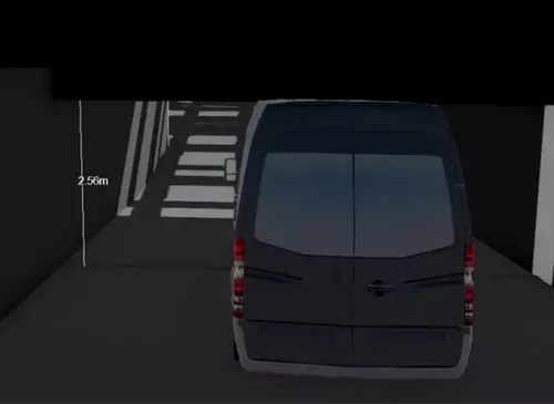
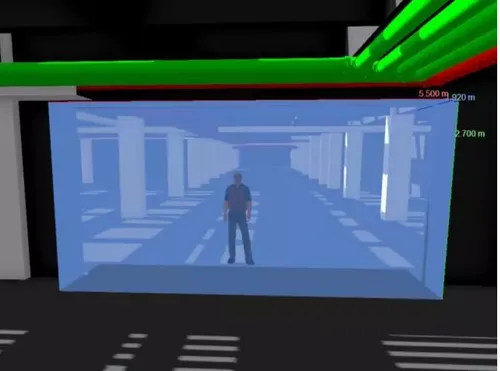
The basement’s first floor requires a minimum clear height of 2.4 meters in lane sections. However, the original design set the lowest pipeline elevation at 2.2 meters, falling short of this requirement. After comprehensive pipeline optimization via the BIM workstation, a 2.4-meter-tall vehicle was used to simulate traffic through lanes and ramps. Clear height checks were conducted, and collision points were recorded and adjusted to ensure compliance with clearance standards.
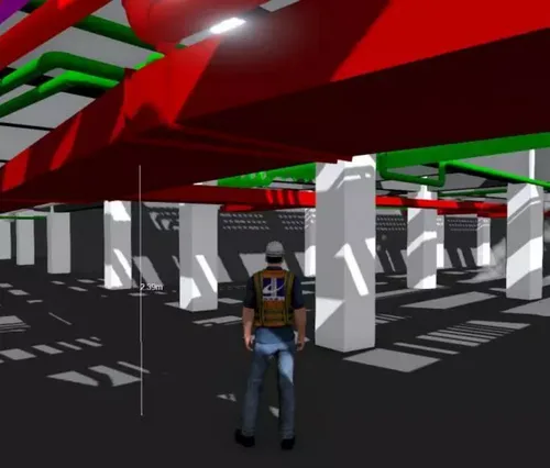
Additionally, personnel with a height of 1.8 meters simulated inspections of pipeline bottom elevations in areas outside the first basement floor, including densely packed zones beyond the roadways, machine rooms, and equipment rooms. Pipelines not meeting elevation requirements were adjusted in real time.

Upon completion of these adjustments, vehicle and personnel traffic simulation videos were produced to demonstrate the results to the client.
Fireproof Rolling Shutter Optimization
During BIM modeling, it was discovered that multiple cable trays and pipelines passed directly through fireproof rolling shutters in the basement, hindering their operation. Three solutions were implemented:
(1) Pipeline routes were optimized and adjusted to avoid crossing the fireproof rolling shutters directly.
(2) For pipelines that could not be relocated, the installation height of the rolling shutter drum was lowered from the original design to the upper space to accommodate the pipelines. The area between the bottom of the beam and the drum was sealed with rolling shutter material, allowing pipelines to pass through openings that provide fireproof sealing. Due to a required net height of 2.4 meters, the drum’s installation height could only be reduced by a maximum of 300 mm.
(3) For a fireproof rolling shutter with a 7.5-meter roll width, after consultation with the client and design institute, the width was reduced to 6 meters. A 1.5-meter-wide wall was designed adjacent to it, through which the pipeline would pass with appropriate fireproof sealing.
By combining these three methods and using walkthrough simulations to verify drum height, the issue of pipelines crossing fireproof rolling shutters was effectively resolved.
Drawing Verification Based on Electromechanical Optimization Model
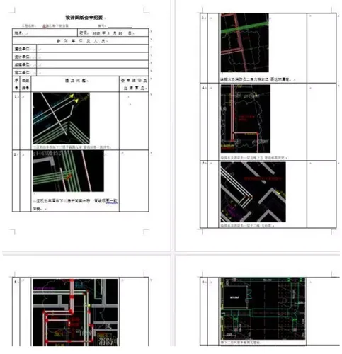
During modeling, a detailed comparison with installation drawings uncovered numerous issues, including:
1. Incomplete pipeline systems and incorrect labeling, such as duplicate riser numbers and inconsistent numbering between upper and lower riser layers.
2. Pipeline bends designed with upward or downward flips; downward flips risk water and debris accumulation and complicate drain valve installation.
3. Unreasonable pipeline layouts, with some water pipes running parallel above electrical bridges.
4. Pipes blocking air vent positions.
5. Missing detailed plans for computer rooms.
6. Strong and weak current cable trays positioned too close, which can cause electromagnetic interference. A minimum vertical clearance of 250 mm between upper and lower cable trays is recommended. When sharing bridge frames, a minimum 300 mm distance between strong and weak trays is advised, with spacing between similar trays maintained between 50-100 mm.


Must log in before commenting!
Sign Up