Leveraging BIM technology, a 3D visualization design environment along with a 4D virtual simulation environment has been developed to explore methods and processes for BIM-assisted visualization design and virtual simulation of construction plans. This approach includes principles for designing 3D digital models of the environment, structural components, and construction facilities within construction plans. Taking into account the specific characteristics of railway tunnel arch and arch filling construction, BIM-assisted visualization design is applied to create a three-dimensional digital model of the construction scheme. This model aids in optimizing the design of rapid construction equipment and techniques for the arch and its filling, as well as simulating the construction process. The results demonstrate that BIM-supported optimization of railway tunnel construction schemes yields positive outcomes.
1. Overview
With the swift advancement of high-speed railway infrastructure in China, particularly the standardization of railway tunnel construction, traditional methods for arch and arch filling are no longer adequate. These conventional techniques fall short in meeting evolving technological demands and quality expectations concerning appearance, structural dimensions, linear control, and efficient arch concrete construction.
Currently, composite lining tunnels in railway mines often rely on assembling small templates for arch and arch filling. This method is marked by high manual labor costs, limited equipment and tooling, and subpar construction quality. Progress is difficult to maintain, which impacts the overall construction timeline. In addition, this can lead to safety step distances exceeding standards during tunnel face excavation, negatively affecting the structural connections and delaying subsequent steps such as waterproofing and secondary lining. Consequently, the inverted arch and its filling have become critical processes that restrict the quality and speed of tunnel construction.
BIM technology, grounded in 3D digital models, replaces traditional linear design based on single views with linked flat, vertical, and sectional 3D model views. It transforms 3D design concepts into tangible three-dimensional objects, enabling a “what you see is what you get” visualization environment. By combining BIM models with virtual reality technologies, plans can be presented comprehensively and interactively, allowing thorough review and validation of their rationality. This includes a method and process for displaying plans within a 4D virtual simulation environment.
Given the current challenges, applying BIM technology for visualization, collaboration, simulation, and optimization offers significant potential for the rapid design of construction equipment and processes related to tunnel arch and arch filling.
Principles of BIM-Based Construction Scheme Design
Traditional construction plan development depends heavily on interpreting two-dimensional drawings, combined with past experience and subjective choices of equipment and processes. This approach often results in inappropriate equipment selection, overly complex or impractical processes, and common issues such as errors, omissions, and clashes in detailed design drawings.
In contrast, BIM’s 3D visualization and 4D virtual simulation environments provide technical means to optimize equipment and process design while verifying feasibility. The core of achieving 3D visualization and 4D simulation is establishing an accurate three-dimensional digital model that fully represents the construction plan. This includes:
- Environmental Model: Virtual layout of the site, pre- and post-construction processes, and other environmental factors influencing the plan.
- Structural Model: Virtual representation of the engineering structures involved in the plan.
- Construction Facility Model: Mechanical equipment, templates, molds, and other operational tools used during construction, which are key to BIM-assisted design.
By dynamically linking the components of these models based on the construction sequence and associated tasks, the virtual construction process can be simulated through time-driven model components.
Using Autodesk Revit and Navisworks software, the visualization design process follows these steps:
(1) Create a 3D digital model in Revit, assigning unique construction sequence parameters to each component, then export the model as an NWC file;
(2) Use Excel to manage the schedule of construction tasks—including task names, types, start and end times, and ID numbers—and export as a CSV file;
(3) Import the NWC model and CSV task data into Navisworks, apply automatic association rules to link model components with time tasks one-to-one, and perform 4D virtual construction driven by the timeline within the simulation environment.
Figure 1 illustrates this BIM-based visualization design process for construction plans.
Within the BIM 4D simulation environment, real-time interactive simulations allow dynamic feasibility checks and identification of issues during virtual construction planning. This facilitates optimization of equipment and processes, as shown in Figure 2.
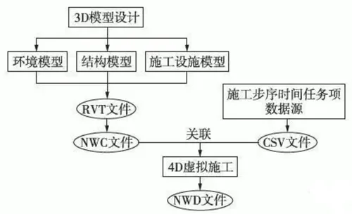
Figure 1: Visualization Design Process of Construction Scheme Based on BIM
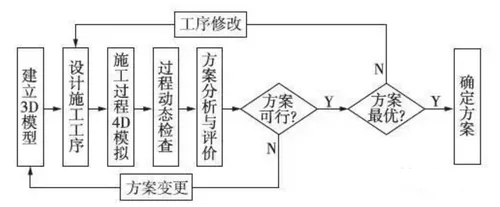
Figure 2: Optimization Process of Construction Scheme Based on BIM
Collaborative Design of 3D Models
The collaborative design principle involves first creating an environmental model based on the site’s conditions to establish a realistic virtual design environment. Next, a structural model is developed, incorporating unbuilt structural elements within the existing environment. Lastly, within the constraints of the environmental model’s working space and aligned with the structural model’s construction needs, the construction facility model is designed and optimized through visual design and virtual simulation. This integrated approach achieves effective collaborative design of the overall construction plan model.
For tunnel arch and arch filling construction plans, Autodesk Revit is used to establish three key models:
- Environmental Model: Includes the tunnel’s initial support and the soil and rock at the front arch bottom.
- Structural Model: Represents the inverted arch and arch filling.
- Construction Facility Model: Comprises the rapid construction trolley used for the inverted arch and arch filling.
3.1 Environmental Model
The tunnel’s initial support and excavation of soil and rock at the front arch bottom are preparatory construction steps for the inverted arch and filling plan. Based on construction drawings of the taro grade surrounding rock lining section and adhering to process division principles, a model for the initial support and arch bottom earthwork is created, as shown in Figure 3.
It is important to note that the initial support model serves as a static construction environment layout and does not participate in the virtual deduction process. Conversely, the arch bottom earthwork model reflects the dynamic excavation process and includes assigned construction step parameters. Component modeling accuracy follows the principle of dividing the tunnel into 6-meter sections along its axis.
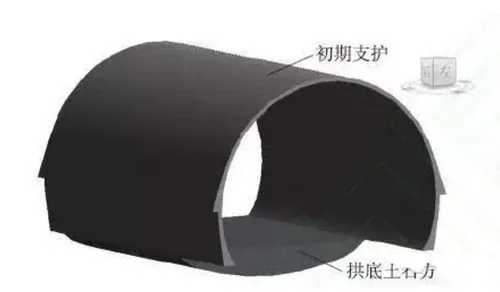
Figure 3: Initial Support and Arch Bottom Earthwork Model of Tunnel
3.2 Structural Model
Following the taro grade surrounding rock lining section drawings and process division principles, a tunnel inverted arch and arch filling model is established, as shown in Figure 4. The inverted arch’s low side wall extends 300mm above the filling surface and includes a reserved center cover groove.
The inverted arch is constructed from C30 concrete, while the arch filling uses C20 concrete; both are poured independently. Construction sequence parameters are assigned to model components, and modeling accuracy follows the 6-meter tunnel section division along the tunnel axis.
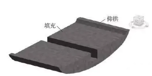
Figure 4: Tunnel Inverted Arch and Arch Filling Model


Must log in before commenting!
Sign Up