Abstract
The China Huarong Building project is a super high-rise structure featuring a hyperbolic cut shape. It integrates commercial, office, and hotel functions, resulting in a complex mechanical and electrical pipeline system with an intricate layout. This complexity requires frequent coordination and communication across multiple disciplines.
1. Project Background
1. Project Name: China Huarong Building Project
2. Project Design Unit: China Electronics Engineering Design Institute
China Electronics Engineering Design Institute (CEEDI) is a comprehensive engineering construction group and a member of the International Federation of Consulting Engineers in China, as well as the International Pollution Control Association Alliance. It ranks among the top ten backbone survey and design units managed by the central government, holding Class A national certifications in engineering consulting, design, contracting, supervision, cost consulting, and electronic engineering professional contracting. CEEDI obtained ISO9001 quality system certification in 1997 and provides full-process planning consulting, feasibility studies, engineering design, construction, supervision, and general contracting services across industrial and civil construction projects.
3. Related Software Applications:
- Autodesk Revit Architecture
- Autodesk Revit Structure
- Autodesk Revit MEP
- Autodesk Navisworks
- Autodesk Ecotect Analysis
- Autodesk Project Vasari
- AutoCAD Civil 3D
4. BIM Application Evaluation and Feedback:
“A key aspect of BIM technology is the high consistency between users and designers. Only when designers integrate BIM into their design process can the full benefits of collaborative design, improved quality, and efficiency be realized. BIM teams and designers are the future direction of BIM technology in design institutes.”
— Zhang Chengge, Deputy Director, Second Institute of Architecture and Research, CEEDI, National First-Class Registered Architect
“Autodesk’s BIM technology represents a technological revolution in construction, following the CAD era. It will transform the entire construction industry workflow. As new technology arises, we must maintain clarity, focus on application research and standardization, and ensure steady development through practice.”
— Xie Wei, Deputy Chief Engineer, CEEDI
“In complex architectural designs, Autodesk BIM-based software offers irreplaceable advantages. BIM significantly enhances design quality and adds value for owners. With ongoing development, BIM will soon replace 2D design, revolutionizing engineering design and management.”
— Wu Yaohui, Chief Engineer, Second Institute of Architectural Design and Research, CEEDI, National First-Class Registered Structural Engineer
2. Main Text
China Huarong Building – Full Professional and Full Process BIM Platform Application
Project Overview
The China Huarong Building project is located in the Port Service Area of Hengqin New District, Zhuhai City. Developed by Huarong Real Estate Co., Ltd., with detailed and construction drawing design by CEEDI, the project covers a total land area of 19,926.24 square meters and a total construction area of 150,062.05 square meters. The above-ground construction area spans 100,982.17 square meters, with 49,079.88 square meters underground. The plot ratio is 5.03.
The above-ground podium has three floors with a height of 18m. The main hotel tower (#1) comprises 32 floors, reaching 144m to the roof structure and 150m to the curtain wall top. The office tower (#2) has 22 floors, with roof and curtain wall heights of 100m and 106m respectively. There are three underground floors, extending 15.35m below ground.
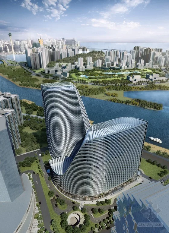
Figure 1: Architectural Rendering
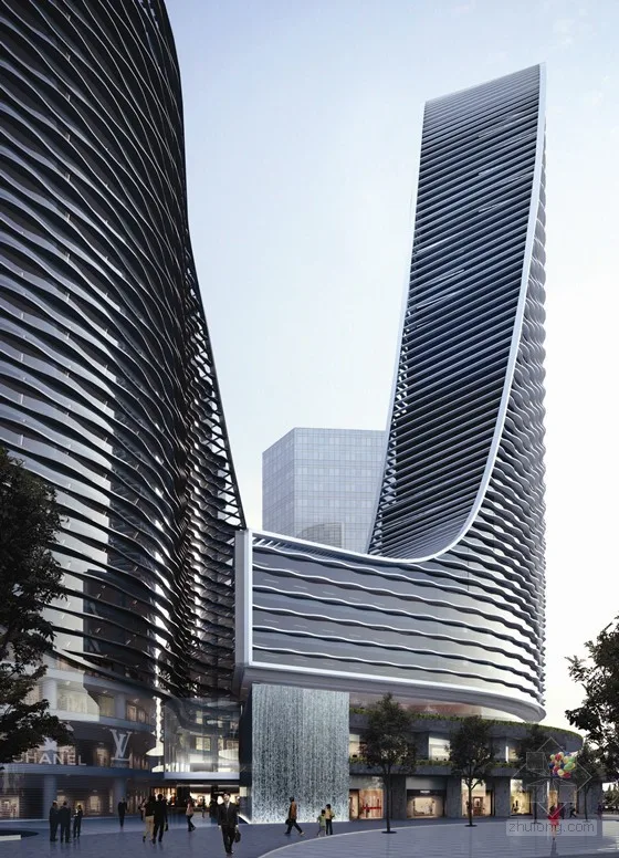
Figure 2: Architectural Facade Rendering
Project Challenges and Solutions
This super high-rise project features a novel hyperbolic cut design and combines commercial, office, and hotel uses, resulting in complex pipeline systems within the mechanical and electrical engineering disciplines. The comprehensive pipeline layout is intricate, necessitating frequent coordination and communication across different professions.
To address these challenges, CEEDI employed a full professional BIM platform for 3D design, enabling comprehensive coordination across all disciplines.
BIM Platform Design Process Overview
The 3D design process involved splitting the BIM model by project sections, professional 3D collaborative design, inter-disciplinary collaboration, and full 3D collision detection across specialties.
Based on the schematic design provided, CEEDI analyzed and segmented the building model by volume and function. The project was divided into two parts: above ground and underground, based on function distribution, building volume, shape, and design team size. Two designers focused on the underground garage and hotel service management rooms; above ground, designers were assigned to the office and hotel towers separately.
Two central files were created for above and underground sections. Professional information sharing and referencing occurred via “Autodesk Revit file links” between these sections. Each central file was subdivided into multiple working sets to facilitate collaboration.
For the above-ground section, six working sets were defined: shared grid and elevation, hotel tower, office tower, floor slab, exterior facade curtain wall, and podium. The underground section was divided into three working sets: shared grid and elevation, basement A area, and basement B area. This approach enabled the completion of the building’s comprehensive 3D model.
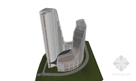
Figure 3: Architectural Professional Model
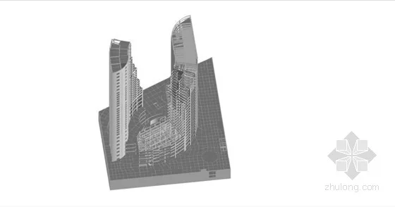
Figure 4: Structural Professional Model
This “working set” collaboration enables designers to update and access the latest information promptly, facilitating efficient information sharing and improving design productivity.
The mechanical and electrical disciplines used the base building model as a reference to build their professional models. Throughout the modeling process, designers continuously checked for clashes between mechanical/electrical components and structural elements, as well as within their own systems. This allowed timely resolution of conflicts, boosting efficiency. The 3D visualization also helps designers intuitively understand pipeline spatial layouts, offering multiple layout options.
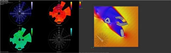
Figure 5: Water Supply and Drainage Model Figure 6: HVAC Model
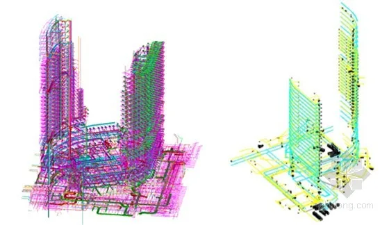
Figure 7: Electrical Model Figure 8: Complete Mechanical and Electrical Model
During 3D collaborative design, BIM software’s built-in clash detection tools were used for inspections. Each discipline first resolved internal model conflicts using Autodesk Revit. Once internal issues were cleared, all professional models—architecture, structure, plumbing, electrical—were linked and merged into a comprehensive model.
This comprehensive model was imported into Autodesk Navisworks for pipeline clash detection, generating detailed reports. The Navisworks model correlates with the Revit model, allowing identified clash points to be quickly referenced and corrected in Revit, streamlining the modification process.
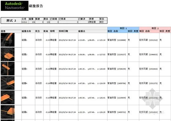
Figure 9: Collision Detection Report
BIM Platform Value Summary
BIM transforms abstract 2D drawings into intuitive, understandable 3D models, enabling both professionals and non-professionals to accurately assess project design rationality. Complex elements like stairway spaces, vertical pipeline layouts, and pipeline-structure collisions become visually identifiable and solvable through 3D models.
3D visualization also allows simulation and animation of complex construction processes, facilitating faster and more convenient installation for construction teams.
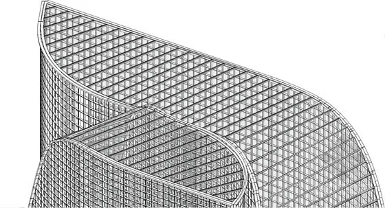
Figure 10: Roof Curtain Wall Grille Diagram
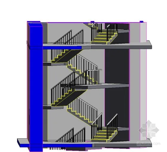
Figure 11: Staircase Space Section Diagram
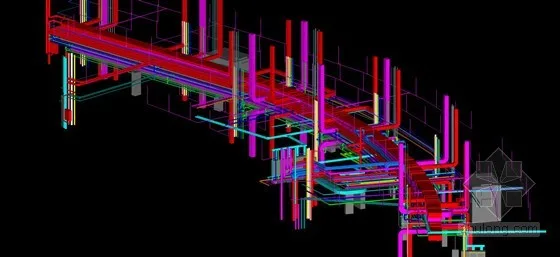
Figure 12: Comprehensive Pipelines on 20th Floor Refuge Layer Diagram
Using BIM technology, local spatial optimization design was achieved. Traditional 2D design struggles to detect collisions between walls and roof grilles through plans and sections. However, 3D visualization makes errors easily identifiable, enabling design optimization and improved communication among design teams.
During 3D collaborative design, independent design results from multiple disciplines and team members were periodically unified on the same 3D platform for clash detection. This process helps prevent unnecessary design errors caused by misunderstandings or delayed communication.
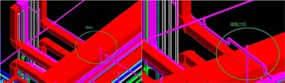
Figure 13: Before Pipeline Collision Adjustment Figure 14: After Pipeline Collision Adjustment
In conclusion, BIM application during the design phase effectively addressed project challenges, enhanced design quality and efficiency, and clearly demonstrated BIM’s value in visualization, parameterization, and collaborative design.
Building Performance Analysis
The China Huarong Building project utilized Autodesk Ecotect Analysis and Autodesk Project Vasari to optimize architectural design by:
- Analyzing the local climate environment
- Evaluating shadow impacts between the building and surroundings
- Tracking annual shadow changes on the building
- Conducting thermal radiation analysis for indoor functional spaces
- Assessing indoor lighting distribution
- Analyzing exterior curtain wall sunshade panels
- Simulating wind environment and airflow around the building
These analyses guided design improvements to meet green and energy-saving standards.
Figures 15-20 illustrate local climate data for Zhuhai, the project location.
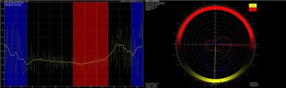
Figure 15: Annual Total Solar Radiation Figure 16: Optimal Building Orientation
Figure 17: Annual Wind Speed, Temperature, Humidity, and Rainfall Figure 18: Airflow Vortex Between Buildings and Surroundings
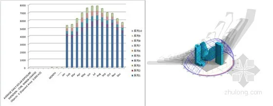
Figure 19: Annual Temperature Radiation Bar Chart Figure 20: Sunshine Shadow Distribution
By analyzing curtain wall heat distribution and sunshade shading, the curtain wall design was refined to align with the building’s overall volume and optimize sunlight control. Without sunshades, overheating could occur; adding sunshades reduces direct solar heat on glass surfaces.
The curtain wall features low-radiation glass and curved sunshades. The spacing and wave shapes of the sunshades are based on the summer sun’s high angle, with their depth carefully calibrated to minimize shading while preserving open views from inside the building.
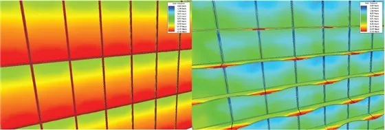
Figure 21: Thermal Radiation Distribution Without Sun Visor Figure 22: Thermal Radiation Distribution With Sun Visor
Outlook
CEEDI envisions the BIM platform as a comprehensive design information processing center that enables direct summarization, transmission, and sharing of information. All models would be built on a unified platform for integrated processing, allowing seamless output of design results. This unified information platform would provide all project stakeholders with the data they need.
CEEDI hopes to expand BIM platform design to more projects, develop BIM standards tailored to China, and continuously improve the BIM design process.


Must log in before commenting!
Sign Up