Authors: Jie Shasha, Jin Pengfei, Wang Lichao from Tianjin 20th Metallurgical Construction Co., Ltd
Introduction
With the rapid advancement of national engineering informatization, construction enterprises are increasingly adopting information technology, driving innovation in construction methods and management practices. During the 12th Five Year Plan period, China progressed toward widespread adoption of construction enterprise information systems, accelerating the use of new technologies such as Building Information Modeling (BIM) and network-based collaboration in engineering projects.
Despite the rapid growth of China’s infrastructure industry, concerns have grown regarding the operation and maintenance of infrastructure assets as projects move from rapid construction into long-term operation phases. Technologies like 3D collaborative design, mobile information access, and cloud computing have emerged as effective solutions to these challenges.
In the evolving engineering design landscape, transitioning to 3D collaborative design alone is no longer sufficient. There is an increasing need to integrate comprehensive data into construction processes to support later stages, such as operation and maintenance. As a construction enterprise, we receive design data during the design phase, transform and optimize it in 3D during construction, and ultimately deliver complete and intuitive data for the owner’s operation and maintenance phase. This process leverages data to significantly reduce construction costs and improve on-site guidance.
Based on the promotion and application of BIM technology, this article presents a case study of a 600m² sintering machine project in Liaoning Province, showcasing the use of the ProjectWise platform in 3D modeling workflows and construction management.
1. Project Overview
1.1 Project Background
China is a leading steel producer globally, consistently ranking first in steel production for several years. The data in the table below illustrates China’s growing share of global steel output. This project focuses on developing a new iron ore smelting process, a milestone with significant implications for both China’s steel industry and the global market.
The sintering plant integrates advanced exhaust gas purification technology, achieving smoke and dust emission concentrations below 30 mg/m³ and effectively removing harmful components. The process facilities are strictly enclosed to recycle waste gas, reducing energy consumption in sintering. Hot waste gas is circulated for waste heat recovery and power generation, further reducing energy use in production processes. From both immediate and long-term perspectives, this project is vital for optimizing resource allocation, advancing sintering technology, and promoting sustainable societal development.
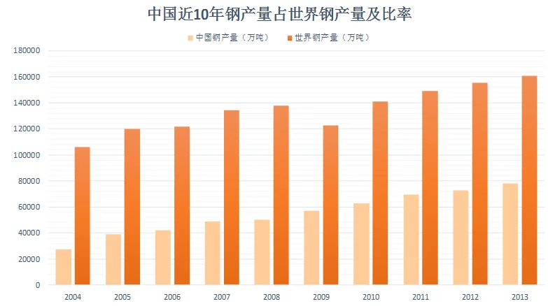
Table 1: China’s steel production over the past 10 years as a proportion of global steel output
1.2 Project Introduction
Located in a city within Liaoning Province, China, this project features a 600m² sintering machine for processing raw materials. It is the largest sintering project in the country, consisting of one 600m² sintering machine with a production capacity of 1,430 tons per hour. The machine incorporates a novel double-sided bellows structure, with a trolley width of 5.5 meters and a single-rod crusher at the tail end. The center distance between the head and tail chain wheels measures 123.35 meters. The sintering speed ranges from 1.3 to 3.9 meters per minute. The total mass of the machine is 3,195 tons, including 173 trolleys weighing a combined 2,048 tons. The effective sintering area is 600m². Figure 1 below shows the 3D model of this sintering project.
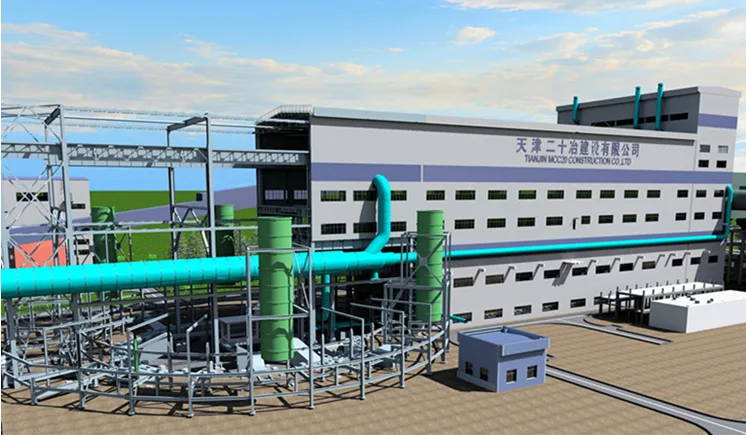
Figure 1: 3D model of the 600m² sintering project
2. Project Implementation Process
This project is designed for construction enterprises characterized by high specialization, mobility, and distributed work locations. The professional design encompasses six key disciplines: architecture, structure, equipment installation, electrical, plumbing, and municipal layout. Each discipline utilizes the ProjectWise collaborative platform to complete workflows including independent modeling, regional assembly, professional assembly, engineering assembly, and final result delivery.
The project team is organized by discipline and personnel, managed centrally by the company’s technical center. Key roles include engineering project managers, project technical leaders, BIM project managers, and BIM technical directors. On-site BIM technicians and construction staff work under professional BIM team leaders, designers, and collaborative administrators, as illustrated in Figure 2.
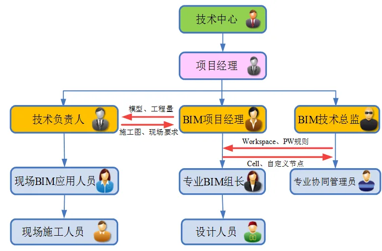
Figure 2: Organizational structure of project personnel
2.1 Workspace Configuration and Model Partitioning
At project initiation, construction staff propose a detailed requirement analysis based on project characteristics. Designers then customize these requirements into workspaces hosted on the ProjectWise platform. This includes AECOsim standards, Bentley Raceway and Cable Management standards, OpenPlant standards, and document standards. By compiling and hosting these standards centrally, all project designers work under unified design requirements and specifications.
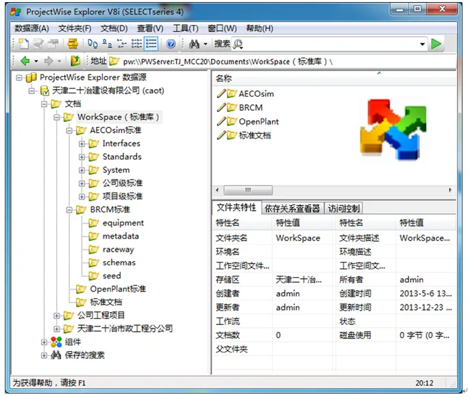
Figure 3: ProjectWise collaborative platform architecture
Models are divided into sections, sub-items, or inspection batches according to project construction requirements or process flow. The project is segmented into components such as chimney, main exhaust fan room, main electrostatic precipitator, sintering main plant, circular cooler, tail electrostatic precipitator, mixing room, bag filter, batching room, finished product screening room, transfer station, finished ore tank room, ancillary facilities, and their integrated pipeline network, as shown in Figure 4.
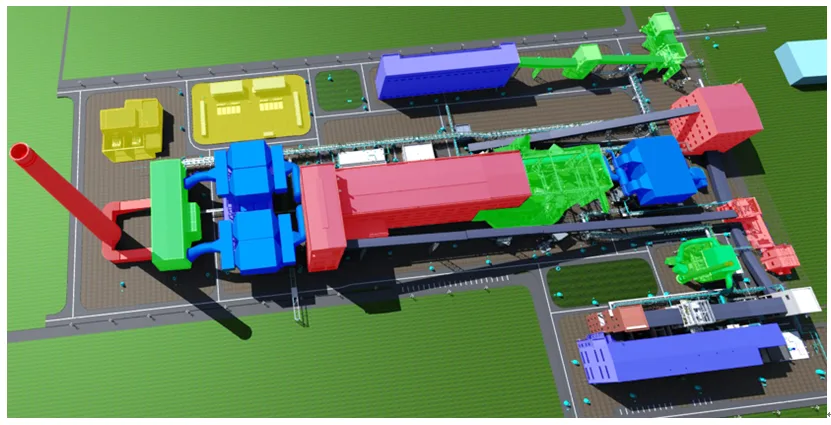
Figure 4: Project model division
2.3 3D Standardization
Drawing on experience from previous projects, the importance of unified coordination and standardized processes has been reinforced. Consistent standards prevent compatibility issues during model assembly, enhance progress and quality in 3D design, and boost overall efficiency.
Project folders and model files are established on the ProjectWise platform with unified configurations at both enterprise and project levels. All designer operations occur on this platform to ensure timely updates. By setting standards for 3D collaborative design, modeling work is standardized and controlled at the enterprise level.
2.4 ProjectWise Collaborative Platform
To address the challenges of remote information management, the project employs a combination of integrated servers, cache servers, and the ProjectWise platform through network technology. This setup enables rapid and effective data sharing among company headquarters, design departments, and construction sites, ensuring real-time data transmission.
For construction sites lacking hardware resources, the browser client of ProjectWise allows personnel to view and download project documents via web access. This facilitates instant extraction, collection, uploading, and dissemination of engineering information across all stakeholders.

Figure 5: Network distribution of ProjectWise collaborative platform
The ProjectWise platform is characterized by a principle described as “One Unified, Five Implementations,” which includes:
- Dynamic user permission management across the entire lifecycle of design, verification, approval, delivery, and service.
- Folder creation, file referencing, check-in, and check-out to ensure file control and uniqueness.
- Independent design across all specialties with seamless multi-level, interdisciplinary collaboration and integration.
- Management of diverse professional software outputs, including models, engineering drawings, reports, views, and materials, enabling multi-level design result classification and archiving.
- Integration of various project participants such as owners, designers, supervisors, equipment manufacturers, and construction teams.
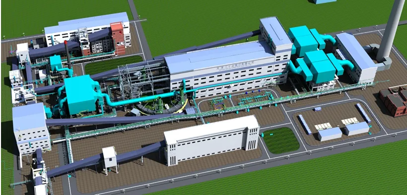
Figure 6: Final assembly rendering of project model
3. Project Applications
3.1 Drawing Self-Review and Joint Review
Using BIM model collision detection, the team conducts thorough self and joint reviews of drawings within and across disciplines. Technical personnel verify the spatial positioning of equipment and pipelines before construction, effectively eliminating issues such as leaks, collisions, and omissions that typically arise during construction. This reduces rework, saves time, and lowers costs.
Computer-assisted inspection via 3D modeling identifies both “hard collisions” and numerous “soft collisions,” including installation space, maintenance access, personnel pathways, pipeline spacing, and equipment layout, which are difficult to detect through manual inspection or traditional 2D designs. The visual clarity of 3D models helps designers optimize plans. This review process identified 235 errors and 67 points of negotiation.
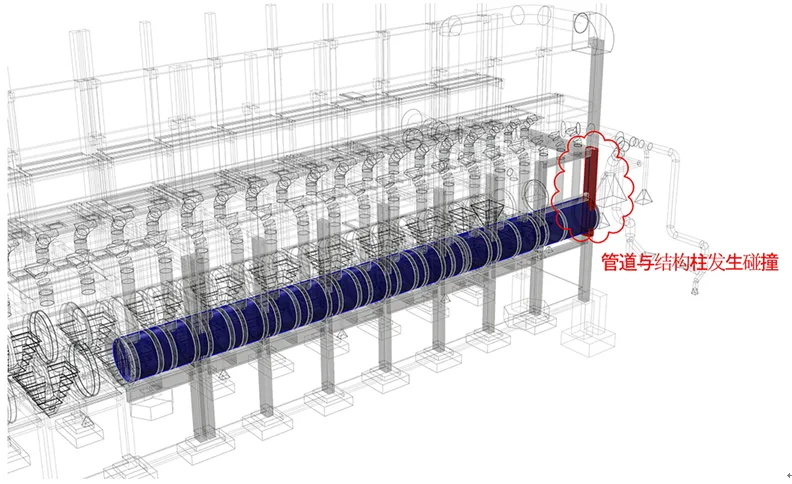
Figure 7: Collision between dust removal pipeline and structure in main factory building
3.2 Quantity Statistics
The BIM-generated 3D model allows for precise material quantity statistics across disciplines including architecture, structure, equipment, and electrical. Automated material reports support efficient procurement, budgeting, and cost control.
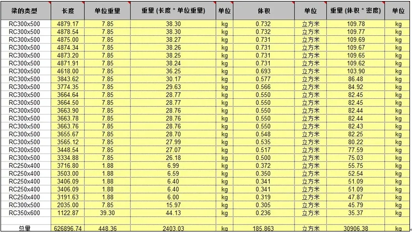
Table 2
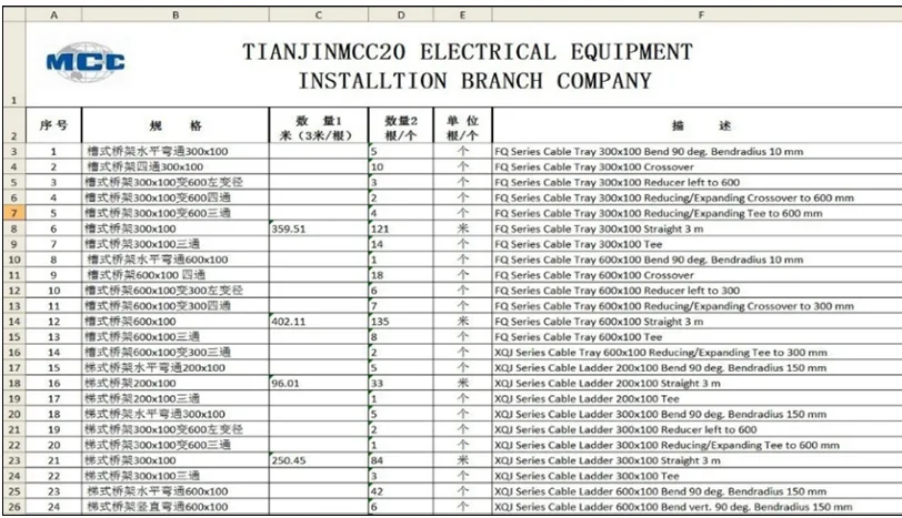
Table 3: Statistical report of electrical equipment materials such as cable trays and bends
3.4 Construction Drawing Production
By sectioning the 3D model, plan views, elevations, sections, and detailed drawings can be directly extracted.
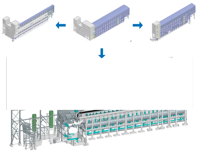
Figure 8: Dynamic cut of the main factory building model
BIM enables extraction of various professional construction drawings and node details, with 3D sectional views created as needed. This overcomes design flaws and spatial blind spots common in traditional 2D drawings. The complete set of drawings covers disciplines such as architecture, structure, equipment, and electrical engineering, including plans, elevations, axonometric views, and stepped sections—facilitating fully paperless construction documentation.
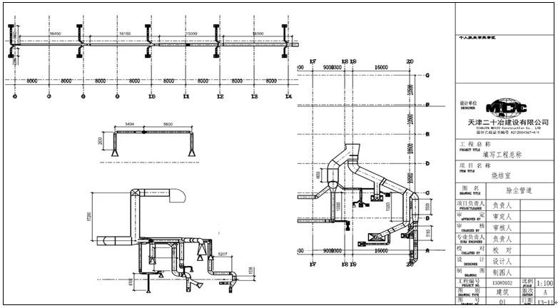
Figure 9: ISO diagram generated by OpenPlant
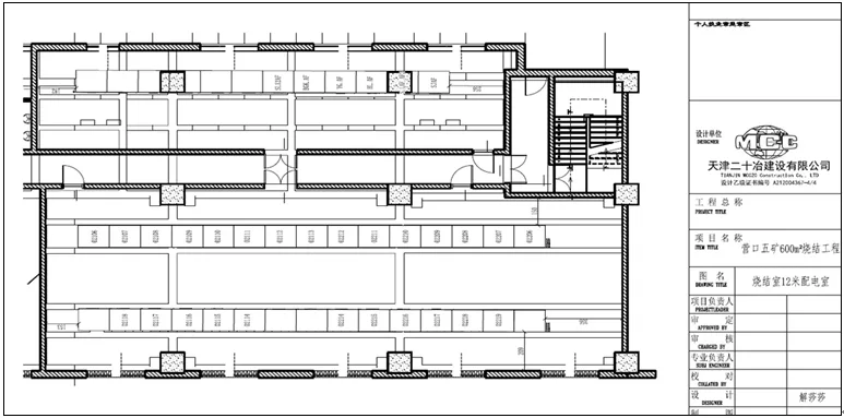
Figure 10: Electrical room equipment layout
3.5 Engineering Applications
3.5.1 Visualization Technology Disclosure
Three-dimensional technical disclosures are provided for complex concrete columns, beam and slab formwork support, and concrete pouring. This includes detailed briefings on masonry assembly, reinforcement retention, and secondary structural columns. Figure 11 illustrates the 3D technical disclosure of shear wall structure formwork, offering an intuitive visual guide that enhances the quality of construction briefings for on-site personnel.
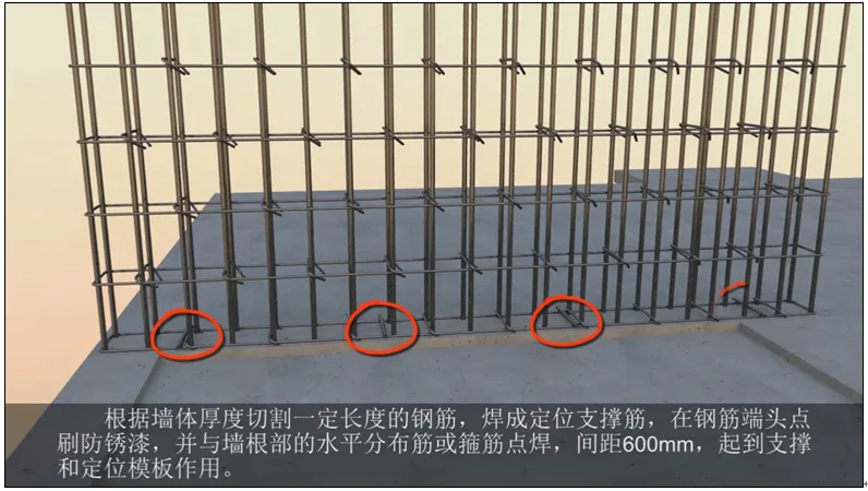
Figure 11: 3D technical disclosure of shear wall formwork
3.5.2 Simulated Construction
Transportation and hoisting of large equipment are optimized using dynamic collision detection within the 3D model to identify any problematic layout in advance. This allows operational and management teams to review and rectify arrangements before construction begins.
The sintering machine’s head wheel weighs 54.9 tons and the tail wheel 34.9 tons, categorizing them as overweight and oversized equipment. Prior to construction, lifting simulations were conducted to guide component transportation and equipment selection. The figure below shows the simulation of lifting the sintering machine’s head wheel.
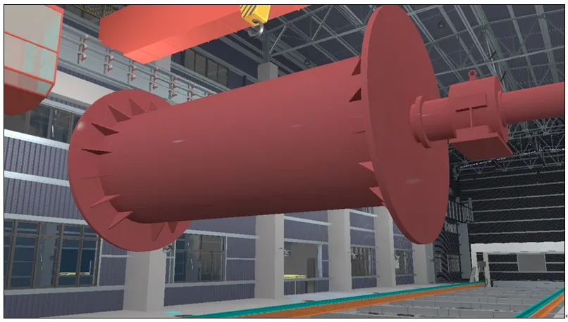
Figure 12: Head wheel lifting simulation in main factory building
The main exhaust fan room’s concrete chimney, at 120 meters tall, uses sliding formwork construction technology. This involves installing a lifting frame inside the chimney, equipped with 32 hydraulic jacks and a hydraulic synchronous control system, and supported by radiation ring beams. The sliding raising process is controlled in 400mm sections, gradually lifting the structure.
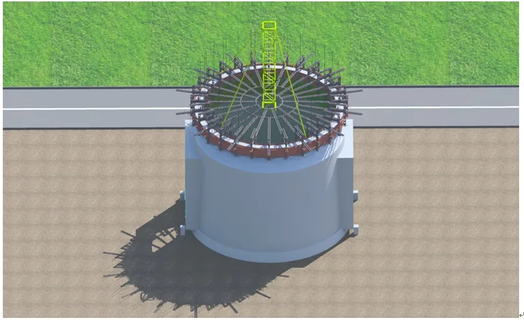
Figure 13: Sliding formwork construction simulation
3.5.3 Construction Progress Simulation
BIM information modeling facilitates 4D project progress control, providing comprehensive visualization of the construction timeline and milestones throughout the project lifecycle.
3.5.4 On-Site Guidance via Handheld Devices
The BIM model can be accessed on iPad handheld devices, allowing personnel to browse, audit, and annotate models in real time. This supports direct comparison between the digital model and physical construction, aiding quality control and guidance. Electronic drawing distribution enables paperless, environmentally friendly construction practices.
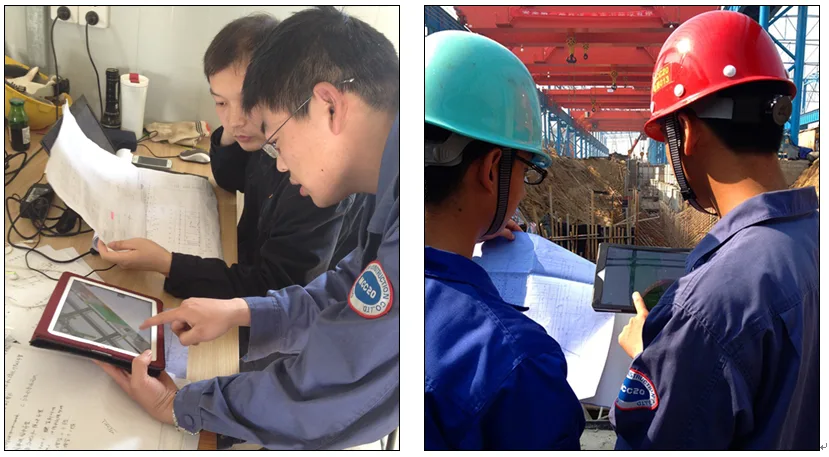
Figure 14: Mobile device application for on-site construction guidance
4. Project Significance
Enhanced Collaboration and Improved Efficiency
The ProjectWise platform facilitates rapid and flexible organizational structuring with all processes traceable and inheritable. Data exchange and publication are controlled and timely, enabling fast design and review cycles. Multiple files and information are shared in real time across management departments, supported by mobile technology.
Reduced Design Errors and Better Quality Management
3D visualization decreases construction errors and improves the front-line team’s understanding of drawings, reducing quality risks. Simulated construction progress optimizes resource use and lowers organizational risks. Automated quantity extraction from 3D models helps control procurement timing and costs, mitigating management risks.
Cost and Operational Expense Reduction
Compared to traditional 2D design, 3D design significantly lowers design and management costs. 3D simulation reduces mechanical shifts, saving machinery expenses. Material statistics derived from models help control supply schedules and prices, contributing to cost savings.
Resource Conservation and Environmental Protection
Implementing paperless technology has saved over 1 million sheets of paper—approximately 4 tons—along with reducing tree felling by 5,526.88 kg, coal usage by 2,036 kg, and water consumption by 141.2 tons. Additionally, CO2 emissions dropped by 14,112.4 kg, SO2 emissions by 83,472 kg, and solid waste by 909.12 kg.
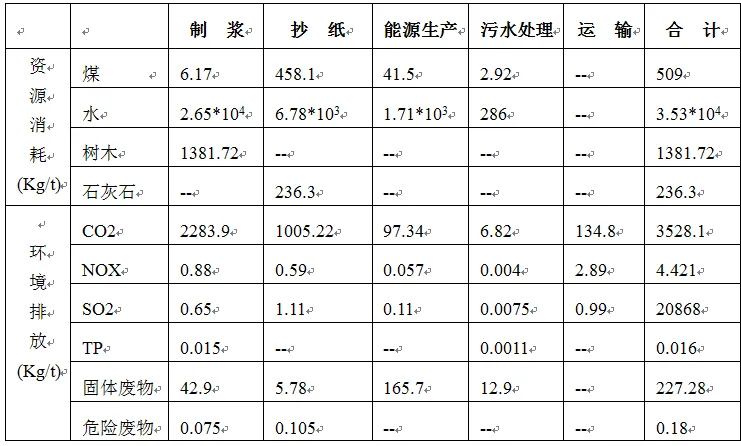
Table 4: Resource consumption and waste generated per ton of paper production
5. Conclusion
The adoption of BIM information management has enabled a leap from 2D to 3D design, bridging information gaps between design, manufacturing, construction, and supervision. It supports pre-construction 3D collision detection and dynamic simulation of construction lifting to minimize design flaws. The automation of quantity extraction from 3D models replaces manual calculations, while 3D technical disclosures improve key construction node management. Digital general layout and ground modeling facilitate the 3D planning of temporary construction facilities. Overall, BIM technology is driving a revolution in construction management and significantly elevates the management capabilities of modern construction enterprises.
References:
__AI_T_SC_0_Zhong Denghua, Song Yang. Research on 3D Visualization Simulation Method for Large scale Water Conservancy Engineering. Journal of Computer Aided Design and Graphics, 2004, 16 (1): 121-127
__AI_T_SC_0_ Li Bo. Three dimensional collaborative design of substations based on ProjectWise. China Construction Information, 2013 (16): 36-39
__AI_T_SC_0_ Dong Yu, Bai Gele, Cao Xiaoyu. Development and Application of 3D Cable Laying Software __AI_S_SC_1_. Inner Mongolia Electric Power Technology, 2008 (2): 39-42
__AI_T_SC_0_Zhao Shunnai. Preliminary exploration of the definition of 3D collaborative design work environment. Central South Water Resources and Power Generation, 2013:29-36
__AI_T_SC_0_Tang Wen, Tian Bin. Research on 3D Visualization Simulation Technology for Hydroelectric Engineering Construction. Hubei Hydroelectric Power, 2008 (4): 23-25
__AI_T_SC_0_Shangzhengfeng. Research on 3D Visualization Simulation and Optimization of Construction Process of Complex Building Complex __AI_S_SC_1_. Tianjin: Tianjin University, 2006
__AI_T_SC_0_ Wei Ying. Realistic Implementation of Three Dimensional Visualization Simulation System for Water Conservancy Engineering. Tianjin: Tianjin University, 2012


Must log in before commenting!
Sign Up