Project Overview
The Cheng Shifa Art Museum represents a significant initiative by the Shanghai Municipal Party Committee and Government, aimed at developing a socialist international cultural metropolis. This project is a key component of the cultural eastward strategy and contributes to establishing a new urban cultural framework centered around one axis and two cultural centers.
As a major cultural construction project during the city’s 13th Five-Year Plan, the Cheng Shifa Art Museum completed its structural topping out by the end of 2018 and is scheduled to open by the end of 2019. The design scheme and construction drawings were developed by Tongji University Architectural Design and Research Institute (Group) Co., Ltd. along with Tongli Design Institute. The building’s exterior reflects the design concept of “stacking the institute and picking up the diameter,” featuring a facade composed of layered stone and glass blocks that create a sculptural effect with a dynamic, staggered appearance.
The museum is located on Hongqiao Road in Gubei District, Changning District, occupying approximately 7,129 square meters of land with a total construction area of 11,500 square meters. It is classified as a medium to large museum, with 7,570 square meters above ground and 3,930 square meters underground. The building rises to a height of 23.85 meters, featuring three above-ground floors housing exhibition spaces, public service areas, and business research rooms, plus one underground floor that includes a lecture hall, parking garage, and equipment rooms.
The underground structure is built with cast-in-place reinforced concrete, while the above-ground portions utilize a steel structure. The design complies with the “National Key Art Museum Standard” and achieves a seismic resistance level of eight. Seismic isolation technology is applied to connect and transfer load between the underground and above-ground structures. Due to the project’s proximity to the subway and limited construction site, the design is complex. The cantilevered above-ground architecture primarily serves as public exhibition space, demanding high standards for spatial effect and comfort. This requires refined steel structure design, optimized mechanical and electrical pipeline layouts, and multidisciplinary collaboration enhanced by BIM technology. Such cooperation ensures efficient space use, meets spatial and exhibition requirements, and optimizes the design within the construction timeframe.
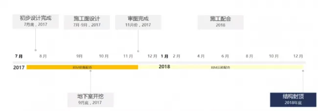
Project Engineering Progress
The BIM team became involved from the early design stage after the project plan was finalized, collaborating throughout the design process until construction drawing review completion, and continued supporting both the design team and the owner during construction.
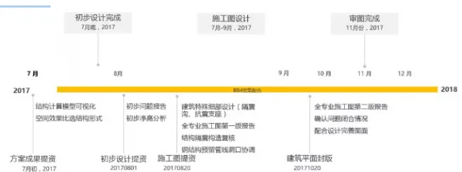
BIM Coordination Timeline During the Design Phase
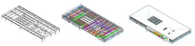
Initial Expansion Stage – Combining BIM with building exterior design and refinement; structural selection, positioning, and dimension optimization.
During the initial expansion stage, the structural model was rapidly generated using computational modeling. By overlaying the existing architectural drawings, the form was closed and visualized in 3D, providing designers with a reliable basis to assess the building’s spatial impact and compare structural options. The following adjustments were promptly confirmed:
- Change the roof truss to steel beams to modify the structural form
- Precisely control the scale of the cantilevered structural components
- Ensure accurate positioning of structural elements during the construction drawing phase, especially the curtain wall boundaries
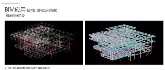
Rapid export of structural 3D models through computational modeling
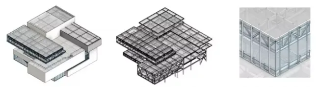
Evaluation of the facade’s visual effects
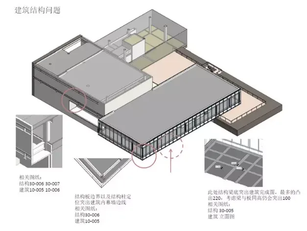
Precise positioning and dimension control of structural components
Construction Drawing Stage – BIM-coordinated seismic structural design
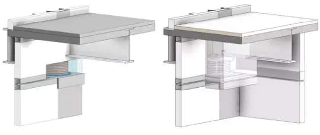
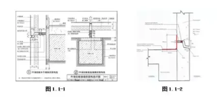
During this stage, BIM was integrated with design efforts to model and analyze seismic isolation bearings. The seismic strategy separates the basement from the above-ground steel structure, minimizing excavation and enhancing overall seismic performance.
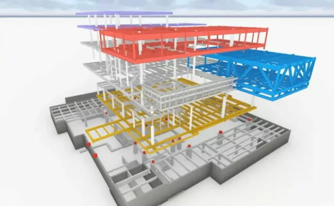
Seismic design illustrating separated aboveground and underground structures
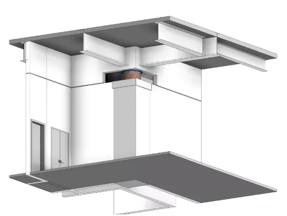
Isolation bearing node detail
Seismic isolation ditch structural node
Throughout the construction drawing phase, each isolation node was modeled in 3D to assist in design decisions and to visualize seismic effects. Particular attention was paid to seismic isolation bearings due to their significant impact on the basement’s indoor spatial experience and the need to meet fire protection requirements. After several conceptual studies, the original plan to use only fireproof materials was revised to include lightweight fireproof partition walls surrounding the bearings.
Revised node design for seismic isolation bearing construction
The updated seismic isolation bearing nodes influenced the basement pipeline BIM model, leading to an overall optimization of the basement design by integrating seismic support nodes.
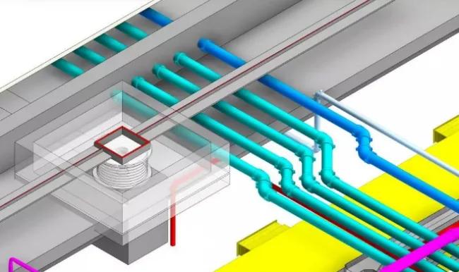
Partial optimization of basement piping coordinated with seismic support nodes
Construction Drawing Stage – BIM-enabled refined spatial management
Following the completion of all mechanical and electrical drawings, pipeline integration and net height verification were conducted for every space.
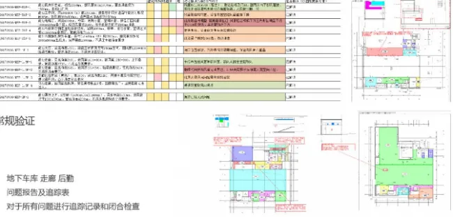
Report on standard pipeline net height issues
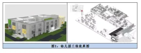
Moreover, given the unique requirements of exhibition spaces, the clear height and routing of exhibition areas were optimized to ensure that internal pipelines remain unobtrusive and do not interfere with the interior décor or exhibition experience.
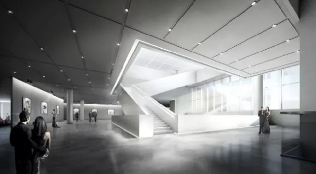
Rendering of exhibition space
Optimization of public corridor pipelines beneath exhibition space stairs
As a public building, controlling the exterior facade’s visual impact is crucial. The BIM team focused on planning equipment installation and pipeline layout for two outdoor equipment platforms to ensure pipelines remain concealed and efficiently arranged.
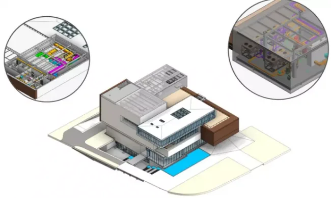
Pipeline verification on equipment platform
Construction Drawing Stage – BIM-supported collaborative design for mechanical, electrical, and structural coordination
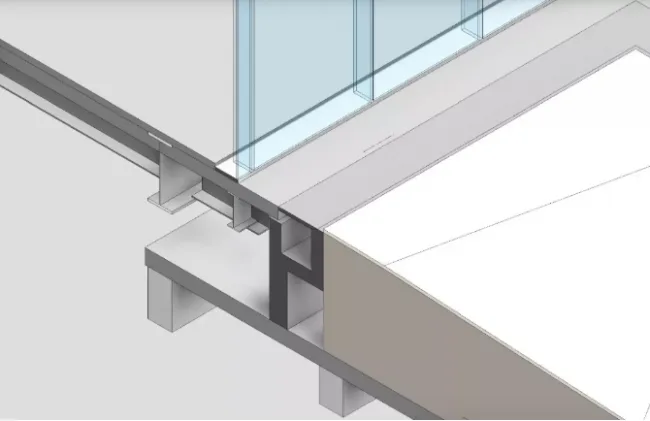
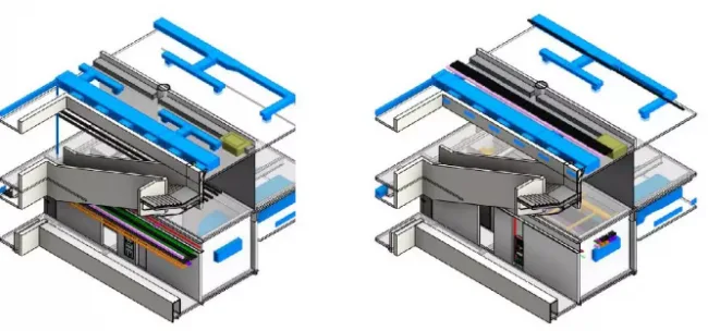
Beyond conventional 2D to 3D verification, BIM facilitated interactive design between equipment pipelines and structural reserved openings within the steel framework.
Due to limited clearance beneath beams in the top suspended space, owner requirements demanded that mechanical and electrical pipelines pass through all beams to maintain the necessary height.
However, strict regulations govern steel structure openings, and multiple disciplines contribute to the mechanical and electrical pipeline design. After extensive coordination, as many openings as possible were reserved within the BIM structural model, respecting steel beam opening principles. The mechanical and electrical teams then managed the pipeline layout comprehensively, accounting for factors such as skylight placement and roof geometry. This approach optimized pipelines while meeting clearance requirements, with unnecessary openings ultimately eliminated. The comprehensive mechanical and electrical model, alongside detailed dimensions and positioning of steel beam openings, was provided to designers as a foundation for final drawings, ensuring coherence and practicality of the integrated design.
Coordination process overview:
Structural hole openings → Mechanical and electrical pipe integration → Window openings to ensure effective space and pipe coordination


Must log in before commenting!
Sign Up