Save costs, accelerate construction timelines, optimize space, and improve quality — BIM pipeline solutions comprehensively support the Yuhou Street Comprehensive Building project.
BIM enables three-dimensional coordination by creating an integrated model that combines architectural, structural, and professional disciplines into a single 3D representation. This approach ensures adequate space for the installation of water pipes, air ducts, fire protection systems, and electrical wiring, effectively avoiding clashes that traditional 2D CAD drawings often miss.
For the Yuhou Street Comprehensive Building, BIM technology helped identify and optimize over 300 collision points, enhancing construction quality, significantly reducing rework, shortening project duration, and lowering costs.
1. BIM Pipeline Solution: Addressing Over 300 Collision Issues and Optimizing Drawings
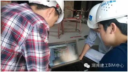
Traditional CAD drawings show only the pipeline’s position relative to beams without elevation details, making construction difficult. BIM was applied during the 3D modeling phase to verify and refine design drawings, conduct clash detection across architectural, structural, and MEP (mechanical, electrical, plumbing) disciplines, and comprehensively plan pipeline layouts. This process ensures accurate pipeline placements and eliminates errors and omissions before construction begins.
Using Revit 2014 for MEP modeling, five major issues were identified and resolved:
- Inconsistencies between the water supply and drainage floor plans and system diagrams;
- Omission of rainwater and sewage piping in system diagrams;
- Discrepancies in HVAC equipment locations;
- Lack of elevation dimensions for air ducts and air conditioning water pipes;
- Overlaps in vertical pipes between two water supply and drainage systems.
Navisworks collision detection identified over 300 clash points. The table below summarizes clashes detected between different disciplines:
| Major Discipline | Number of Collisions |
|---|---|
| Electrical and HVAC | 45 |
| Water Supply & Drainage and Electrical Engineering | 36 |
| Plumbing and HVAC | 242 |
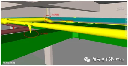
The figure below illustrates the reduction in collision points before and after optimization.
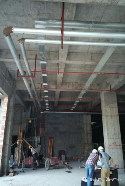
3. Drainage and Exhaust Pipe Optimization
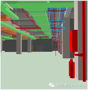
After comprehensive optimization of the pipelines on the first floor of the Yuhou Street commercial complex, all pipeline clashes were resolved, and the layout and construction schedule were efficiently arranged. The electromechanical model of the optimized first floor is shown below.
2. BIM-Based Construction Management
Traditionally, mechanical and electrical installations follow a fixed sequence: fire protection, then water piping and electrical cable trays, followed by HVAC piping. Each specialty is installed independently using single hangers, which wastes space and time while increasing costs.
BIM revolutionizes this process through a workflow that includes:
- Collision detection to identify and resolve pipeline conflicts;
- Integrated pipeline design to optimize layout and reduce waste;
- Accurate quantity takeoff for cost estimation and dispute avoidance;
- Construction simulation and progress control using digital monitoring to ensure quality and schedule adherence.
1. Integrated Pipeline Design
Based on collision reports and construction schedules, the BIM team systematically modified the model to eliminate clashes. Given the building’s low floors and densely packed pipelines, the team optimized the original layout, developing support structures and styles that satisfy aesthetic, clearance, and construction requirements.
Design phase optimizations using BIM can reduce floor height requirements by at least 150mm per level, saving up to 900mm across the entire project and cutting costs by 2% to 3%.
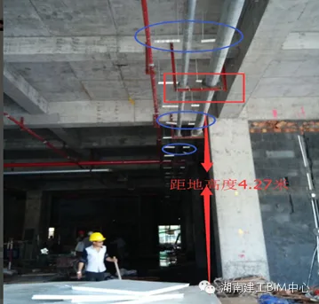
For example, on the first floor of the Yuhou Street project, the traditional single hanger’s lowest point is 4.27m above ground, whereas the optimized comprehensive hanger’s lowest point is 4.42m, achieving a 150mm height optimization. The comparison is shown below.
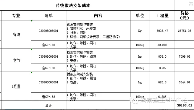
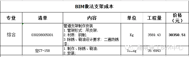
2. Quantity Takeoff and Material Savings
The optimized BIM model reduces bracket usage and labor. Traditionally, single brackets weigh 4,491.97 kilograms. After optimization, comprehensive brackets weigh 3,569.43 kilograms, saving 922.54 kilograms—about 15% material cost reduction.
3. Construction Simulation and Progress Control
BIM links the 3D model with the construction schedule, integrating spatial and temporal data to enhance schedule management. This digital approach replaces traditional methods, ensuring the plan is practical and allowing for synchronized, multi-disciplinary construction, ultimately saving time.
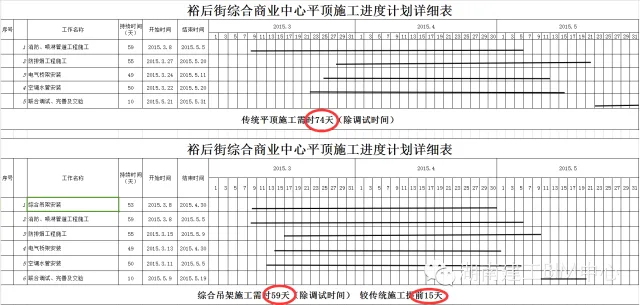
The original roof construction plan estimated 74 days (excluding commissioning), but with BIM, the comprehensive suspension system was completed in 59 days, 15 days ahead of schedule.
3. Comparing 3D BIM and 2D CAD in MEP Engineering
The table below highlights key differences between 3D BIM and traditional 2D CAD drawings in mechanical and electrical engineering:
| Criteria | 3D BIM | 2D CAD |
|---|---|---|
| Positioning | Accurate pipeline elevation positioning with precise net and ceiling height control. | Positioning is limited to the plane. |
| Pipeline Integration | Real-time clash detection with timely adjustments through software. | Relies on experience and coordination among disciplines. |
| Parameterization | Components are parameterized, enabling adjustments reflected in the model. | Separate plans, elevations, sections, and material lists cause design and quantity errors. |
| Coordination | Optimized modeling across disciplines reduces conflicts and errors. | Poor coordination with independent designs leads to uncoordinated results. |
| Material Quantities | Provides real-time, reliable material lists for budgeting. | Manual measurement from CAD files is time-consuming and error-prone. |
| Installation Simulation | 4D installation schedules evaluate design rationality, simplify workflow, and reduce waste. | Lack of compromise among disciplines causes delays and waste. |
| Visualization | Interactive 3D navigation offers clear, real-time insights. | Flat views fragment and distort 3D spatial information. |
| Drawing Analysis | Automated cost calculation and generation of plans, elevations, sections, and 3D views. | Cannot comprehensively and accurately calculate quantities. |
| Cost Management | Reduces costs, limits design changes, and accelerates project timelines. | Longer cycles and higher costs. |


Must log in before commenting!
Sign Up