The high-speed railway project in the western region is designed for speeds up to 250 km/h, covering three provinces and eleven counties. The main line stretches approximately 515 km and includes 14 super-large bridges and 180 extra-long tunnels. The combined length of bridges and tunnels reaches about 405 km, accounting for 81% of the total route. Traversing the steep mountains and rugged terrain of southwestern China, the project faces complex terrain and geological conditions, posing significant challenges to both design and construction.
As a high-speed rail initiative, the project encounters several difficulties: the overall route is quite long, demanding extensive work on route alignment and roadbed cross-section design due to multiple influencing factors. Moreover, the design cycle is notably short—only about six months, which is roughly half the time allocated for projects of similar scale. A key challenge is to evaluate and select among multiple design options within this limited timeframe, while producing high-quality cross-sectional design drawings. The project owner also expects the final design to be presented in a clear and intuitive manner.
To address these challenges, the project leader assembled a BIM design team and implemented BIM technology. This approach enabled seamless collaboration and data sharing across disciplines, enhanced design quality, and provided a more intuitive way to deliver the final design to the owner.
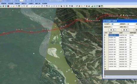
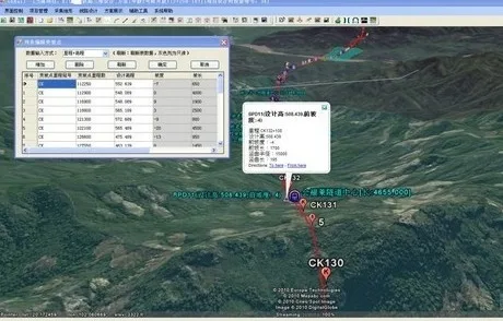
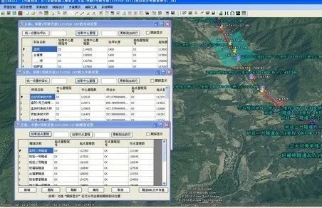
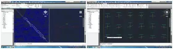
The 3D design process begins with a spatial route selection system based on a 3D GIS platform, which plans the railway’s route corridors and lays the groundwork for subsequent design phases. This system leverages terrain elevation data, imagery, and geographic information from the 3D GIS platform to directly carry out route planning and design. It also provides a comprehensive visualization of the plan, creating a 3D scene along the railway line to facilitate route comparison and selection.
After finalizing the route planning, designers import the horizontal and vertical alignment data directly into AutoCAD Civil 3D software. This enables rapid creation of a 3D model of the railway subgrade based on preliminary alignment selections. The powerful parametric modeling and dynamic update capabilities of AutoCAD Civil 3D allow line and subgrade engineers to work efficiently. Adjustments to horizontal and vertical alignments are reflected in real-time updates to the subgrade model and earthwork volume calculations.
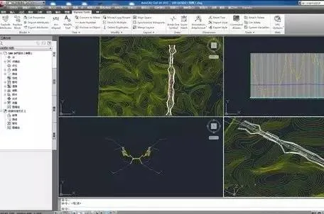
Given the mountainous terrain with significant elevation changes along the route, the cross-section profiles vary greatly. Traditionally, this part of the design process requires substantial time and manpower—for example, designing a 10 km roadbed cross-section typically takes about five days. However, by using intelligent roadbed cross-section components with condition judgment features in AutoCAD Civil 3D, designers can efficiently handle these variations. Furthermore, the cross-sectional drawings and roadbed models are dynamically linked, allowing any modifications to alignments or roadbed assemblies to be instantly reflected in the drawings.
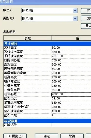
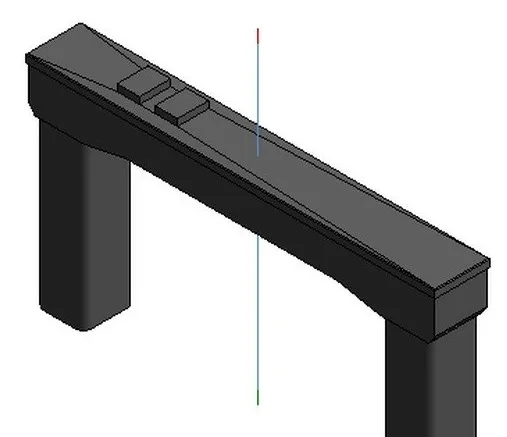
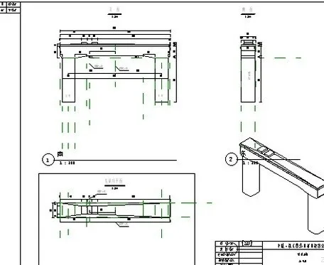
This workflow enables designers to concentrate on the design itself. For this project, approximately 10 days were spent addressing detailed issues such as slope stability, retaining walls, and drainage ditches for the entire 160 km railway subgrade design, with minimal time needed for drawing revisions. Regarding bridge design, designers developed extensive parametric bridge structure libraries using Autodesk Revit Structure, customizing view and schedule templates. Utilizing foundational data like survey results, geological information, and route alignments, designers assemble 3D bridge models from these parametric libraries, quickly generating 2D drawings and calculating concrete volumes.
Additionally, Autodesk Revit’s API was employed to develop a parameterized steel reinforcement configuration module for bridge substructures. This tool automatically arranges solid steel reinforcement for various pier and abutment types, streamlining the production of reinforcement drawings and quantity takeoffs.


Must log in before commenting!
Sign Up