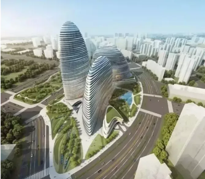
The Wangjing SOHO Center, developed by Souhou China, is a landmark complex located in the Wangjing district, combining commercial and office spaces. Designed by the world-renowned architect Zaha Hadid, with Hardy as the lead designer, the project covers a total construction area of 520,000 square meters. The complex consists of an integrated basement and three towers—T1, T2, and T3. Each tower features curved plans and facades, evoking the natural movement of wind.
The tallest tower, T3, includes four underground floors and 45 floors above ground, with an eaves height of 200 meters and a total construction area of 164,000 square meters (38,000 square meters underground and 126,000 square meters above ground). Its exterior facade and floor plans are defined by irregular, curved lines. The floor areas vary widely, ranging from 780 to 4,000 square meters across floors 1 to 45, with no consistent pattern in the inward expansion of each level. This complexity posed significant challenges for construction, steel structure fabrication, curtain wall installation, and mechanical and electrical systems. As a result, the project demanded high levels of coordination and management from the general contractor.
BIM technology played a critical role in the construction phase by enabling visual control and facilitating collaboration among all stakeholders. It was especially valuable in managing complex spatial coordination for electromechanical systems, steel structures, and curtain wall design, fabrication, and installation, thus ensuring smoother project execution.
Design Optimization and Visual Construction
During the design phase, BIM technology was employed to conduct clash detection among structural, curtain wall, and landscape models based on architectural design requirements. This process helped optimize the design and identify conflicts early.
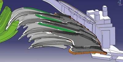
BIM model of Dongxiaxin Square
Integrated Electromechanical Wiring
Due to the building’s unique exterior, the interior tower spaces are irregular, and office designs lack suspended ceilings. Mechanical and electrical pipelines are exposed, requiring meticulous layout planning. Using BIM, the mechanical and electrical teams resolved clashes among water, electrical, and heating pipelines while optimizing the overall pipeline arrangement and enhancing the visual quality of the exposed wiring.
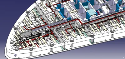
BIM model of mechanical and electrical pipelines
Steel Structure Deepening, Fabrication, and On-Site Construction
The steel columns in this project were curved with no consistent spatial pattern, and steel beams were arranged non-orthogonally. This complexity made detailed design development challenging and demanded high precision in fabrication and installation.
BIM technology was used to refine the design of beam-column connections and steel column intersections, reducing material waste during fabrication and improving on-site installation quality.
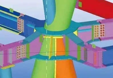
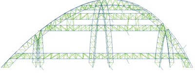
BIM model of steel structure intersecting nodes
BIM model of outer frame steel structure
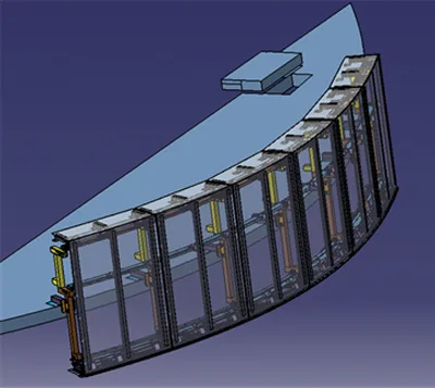
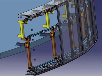
Curtain Wall Deepening, Fabrication, and Installation
The tower’s exterior walls feature glass and aluminum curtain walls, with only a 300–400mm gap between the outer facade and the internal structure. The curved shape results in numerous curved panels, complicating the deepening design and requiring high precision for component fabrication and installation.
The process began by creating detailed node models between the structural framework and the curtain wall skin, based on 2D architectural node diagrams. These models were optimized through collision checks, design specifications, and aesthetic requirements to produce a comprehensive node model. Large-scale modeling followed, generating fabrication and construction drawings, as well as material lists.
The fabrication plant imported CNC machining drawings directly from the BIM model, ensuring component dimensions matched design specifications. Components were numbered according to the bill of materials, enabling direct installation on site following this numbering system.
BIM model for curtain wall deepening design
Digital Construction of the Roof’s Variable Curvature Triangular Truss
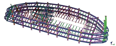
The roof of the T3 tower features a variable curvature triangular pipe truss structure composed of three horizontal trusses, one vertical truss, and four circular trusses, forming a spatial inverted cone that seamlessly integrates with the building facade.
Roof steel structure truss of Wangjing SOHO Center T3 project
1) Digital Information Transmission for Design and Construction
The roof truss supports the roof’s aluminum louvers, requiring the truss’s outer dimensions to align precisely with the facade design—specifically, the structure’s outer contour must be 280mm inside the aluminum panel’s outer edge. Given the strict facade requirements, all aluminum panels were fabricated directly from the BIM model’s processing drawings, demanding highly accurate structural design, fabrication, and installation. Consequently, the entire design was transmitted through the BIM model for precision and coordination.
2) Biomimetic Simulation of Installation
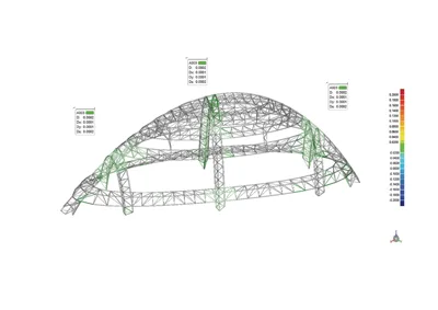
The horizontal truss was assembled as three independent units. Prior to construction, each truss underwent a lifting simulation to verify lifting points and analyze the forces on the truss members and overall structure during installation.
3) Digital Scanning and Assembly Inspection
Each horizontal truss was transported in three sections. To ensure fabrication accuracy, digital scanning and pre-assembly verification were conducted before leaving the factory. Scanning models were compared to the design model to confirm alignment at splice joints and overall machining quality, ensuring the truss’s curved shape met assembly requirements.
After the entire truss assembly, 3D scanning technology was employed to generate a digital model of the roof steel truss. This model was compared with the design model and on-site measurements to detect any deviations during installation and assess scanning accuracy.
Comparison between 3D Scanning Model and Design Model of Roof Steel Structure Dome
Impact and Lessons Learned from BIM Application
The use of BIM technology enabled detailed design development for all irregular structures, achieving 100% design fidelity, especially in steel structure construction, curtain wall installation, and interior decoration. Digital fabrication and construction methods facilitated the creation of complex curved forms, significantly improving fabrication efficiency, accuracy, and accelerating construction progress.
However, challenges remain. Limitations in software capabilities and the absence of comprehensive standards hindered the full application of BIM across all tasks and phases. The diversity of disciplines and use of different software tools created integration issues, such as incomplete overlay of curtain wall models with steel structure models, causing data loss during model merging.
Questions still arise about responsibility for building models that support the entire building lifecycle—not just design review—and how to evolve models to simulate construction processes, guide scheduling, and deliver digital building models upon project completion. Addressing these challenges will require ongoing software development and standardization efforts.


Must log in before commenting!
Sign Up