BIM technology offers two key supports for project management: data and technical capabilities. This article focuses on the application of BIM technology in the technical management of the Xixian Airport project.
Project Overview
The Xixian Airport Comprehensive Bonded Zone Affairs Service Center features a main building with 7 floors above ground and 1 basement level, covering a construction area of 63,081 square meters. The attached building has 3 floors above ground, with a construction area of 7,122 square meters. The total investment is approximately 499.77 million yuan. The structure is a fully cast-in-place steel-concrete hybrid frame, noted for its complex design and high construction difficulty. Industry experts have praised the project as the “Northwest Bird’s Nest” due to its architectural sophistication.
Airport construction projects face numerous challenges: unique shapes, complex structures, and lack of precedents. Most structures involve steel columns with numerous conflicts between steel beams and reinforcement bars, complicating construction planning. The mechanical and electrical installations are intricate, with frequent clashes between installation works and the main structure, making issues hard to detect. Additionally, as a typical trilateral project, the design drawings undergo frequent major changes. Traditional management methods struggle to effectively control construction quality, schedule, and cost. Consequently, the project team introduced BIM technology to address these challenges.
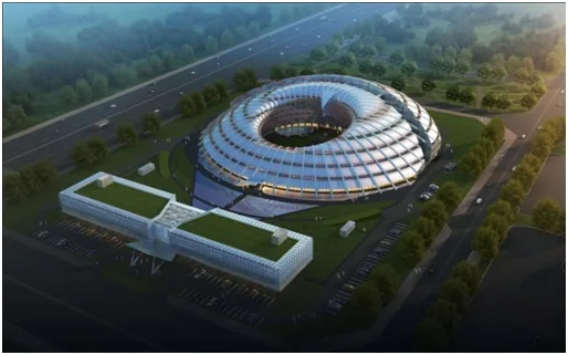
Rendering of the Xixian Airport Project
The project team evaluated several domestic and international BIM software and projects. Key considerations included: compatibility of BIM suppliers with design institutes and construction enterprises, the choice between international or domestic BIM software, and whether to purchase software outright or use a service model. After careful review, the team selected Lu Ban’s full-process BIM services to support project management.
In summary, BIM technology provides crucial data and technical support for project management. This article details its technical management applications on the Xixian Airport project.
Model Creation and Issue Detection
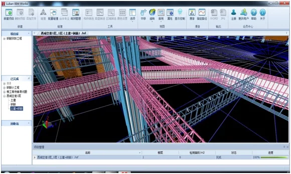
Due to the complex structural design and numerous irregular components in the Xixian Airport project, manual quantity calculations would be time-consuming and prone to errors. Utilizing BIM technology, professional modelers quickly established the project model and accurately calculated quantities, reducing common mistakes.
The civil engineering model took 11 working days to establish and refine, while the steel reinforcement model required 10 working days. Creating these models also helped identify many drawing issues: 45 problems were found in civil engineering and 41 in steel reinforcement through BIM modeling and cloud-based inspections. Early detection of these issues prevented delays and quality problems during construction and ensured accurate project quantities, protecting company profits.
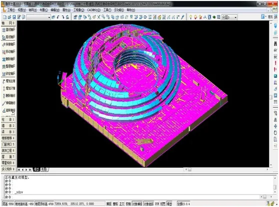
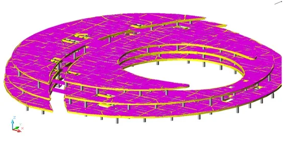
Overall Civil Engineering Model
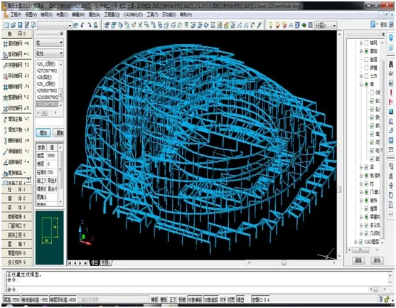
Steel Structure Model (Imported from IFC)
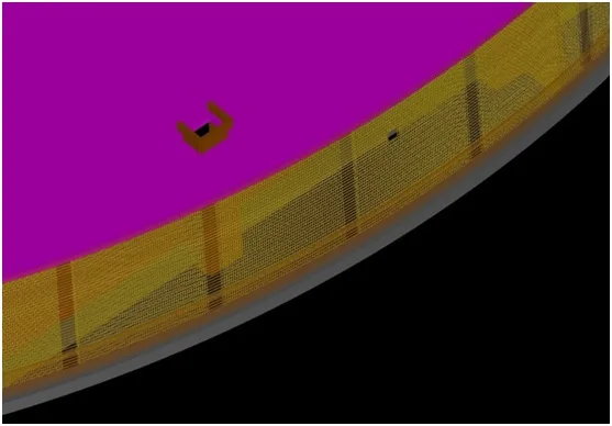
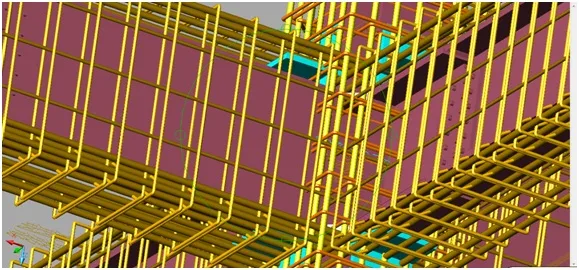
Reinforcement Model of Partial Curved Concrete Wall
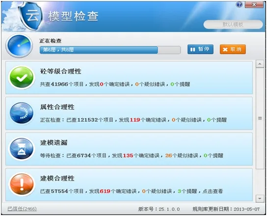
Intelligent Inspection Using Cloud Model Checking
Collision Detection to Eliminate Design Flaws
The project leveraged Luban Cloud Computing to merge multidisciplinary design drawings using Luban BIM Works, identifying conflicts and coordinating modifications with the design institute. This platform automatically detects collision points, quickly locating conflicts across specialties such as steel structure, mechanical and electrical, and civil engineering during construction.
The system automatically identified 446 collision points when integrating the civil engineering and installation models. Estimating an average loss of 500 yuan per collision, early detection saved the project over 200,000 yuan in material, labor, and construction costs.
Collision detection also intelligently locates reserved holes. The final report identified 36 reserved holes in the basement, allowing construction teams to prepare templates in advance, avoiding secondary openings, ensuring quality, and saving labor.
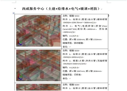
Collision Report
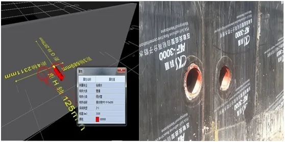
Reserved Hole Positions Guiding On-Site Construction
Pipeline Integration, Layout Optimization, and Construction Guidance
Following collision inspection, Luban BIM consultants and mechanical and electrical engineers adjusted the 3D model according to avoidance principles, construction plans, and requirements for clearance and aesthetics. The integrated model resolved detected collisions, optimized pipeline layouts, and generated 2D plans and sectional drawings to guide on-site construction.
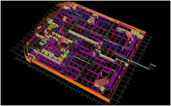
Comprehensive Model of Underground Pipelines
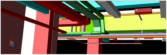
Original BIM Integrated Model
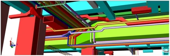
BIM Model After Optimization
Integration and Simulation of Steel Reinforcement and Steel Structures
Beams and columns in the project are primarily steel-concrete composites with complex joints due to varying cross-sectional sizes and abundant steel reinforcement. Integration of steel structure BIM models and steel reinforcement BIM models was essential.
The steel structure model, created using MagiCAD software, was imported into Luban BIM Works via IFC standards. Cloud computing automatically detected conflicts between steel bars and steel structures, and each steel-concrete beam-column node was visualized in 3D.
Collision Between Steel Bars and Steel Sections
This integration visually displays the structural form of section steel and reinforcement at nodes, allowing prediction of construction challenges and potential problems at beam-column joints. This includes method testing, process simulation, and optimization of construction plans, enabling trial runs before actual work, eliminating design errors, and reducing risks during construction.
For example, two types of steel beams—cross-shaped and box-shaped—connect steel-concrete beams and columns. Stirrup size depends on the position of main reinforcements and flange plate bolts. The 3D BIM model revealed that four different stirrup types were used on the same steel column section. Two rectangular stirrups tightly attached to the flange plate’s outer side would be obstructed by bolts, making installation impossible if built per design. Therefore, spacing of the rectangular stirrups must be adjusted to ensure proper installation.
Similarly, beam reinforcement follows the same approach. Column stirrups, originally designed as closed loops, must pass through the steel beam’s web plate at beam-column joints. Closed stirrups cannot fit, so the web plate requires holes, and closed stirrups are replaced with U-shaped ones at these points. After installation, welding of 10d (d = stirrup diameter) at overlaps ensures structural integrity.
Simulation of Column Hoop Reinforcement Scheme
Progress Simulation and Monitoring
BIM technology assigns time schedules to each component, dynamically displaying actual project progress. This enables project managers to maintain comprehensive control. Comparing planned versus actual progress helps identify gaps and critical construction processes affecting the schedule. Improvements can then be made, maintaining cost while preventing future delays.
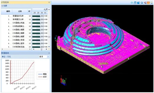
Actual Progress Simulation (Integrated with Cost and Process)

Comparison of Planned vs. Actual Progress
Construction Organization and Coordination to Enhance Communication
BIM integrates various professional models into a complete building information model. Discussions and decisions are based on this unified model, enabling all parties to jointly identify risks and develop solutions. This significantly improves communication efficiency and shortens the plan finalization cycle.
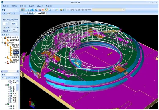
Integration of Structural and Steel Structure Models in BIM Browser
BIM Highlights Areas Needing Edge Protection
Through virtual construction with BIM and model collaboration in the PDS system, areas requiring edge protection are visually displayed in 3D. This enables safety managers to promptly develop protection plans. The airport’s underground level is extensive, with numerous edges and openings. Edge protection includes staircases, stair perimeters, structural edges, roof edges, and construction elevator edges.
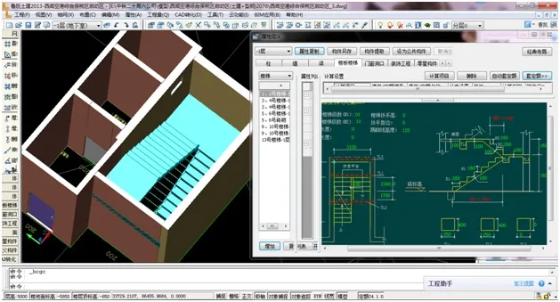
Stair Model and Parameter Visualization
Automatic Retrieval of Tall and Large Formwork to Enhance Safety
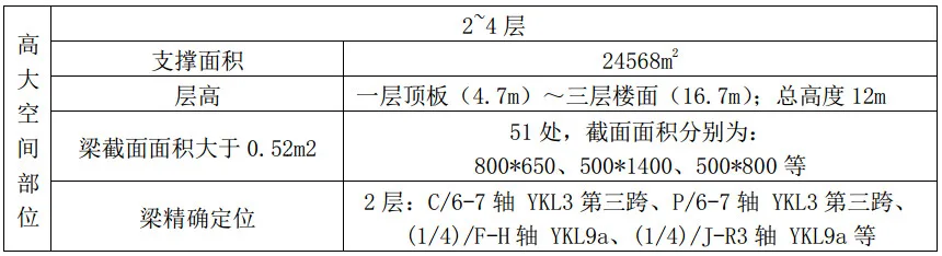
The airport’s basement and above-ground floors have heights ranging from 4 to 5 meters, featuring large-span beams and slabs. Proper implementation of tall formwork is critical for safety and quality. Traditional searches for tall formwork components are time-consuming, but BIM technology allows automatic retrieval, preventing omissions and quickly mitigating safety risks.
Using BIM, 51 beam locations with cross-sectional areas ≥ 0.52 m² and 21 locations with spans ≥ 18 m were identified on floors 2 to 4. Each location is precisely mapped and documented in Excel spreadsheets for on-site personnel to ensure timely and safe construction measures where high formwork support is necessary.
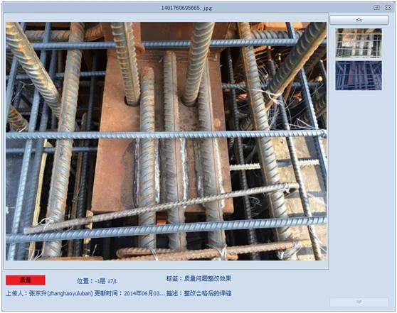
Mobile Quality and Safety Management
Every construction project faces safety and quality issues of varying scales. After implementing BIM technology in the airport bonded zone project, safety and quality personnel used the iBan mobile client to facilitate issue recording, communication, coordination, and timely resolution. This significantly improved work efficiency and helped prevent safety and quality risks.
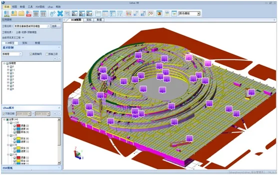
Viewing Uploaded Photos in the BIM Browser
During on-site safety and quality management, hazards are identified and uploaded to the cloud server via iBan, linked to BIM models for precise location tracking. This allows project managers and chief engineers to monitor safety and quality risks remotely and make timely decisions from the office.


Must log in before commenting!
Sign Up