Introduction
Steel reinforcement in buildings functions like a skeleton, connecting various structural components and providing essential support. The quality of reinforcement work has a direct impact on the overall project quality. What key aspects should we focus on during the construction process?
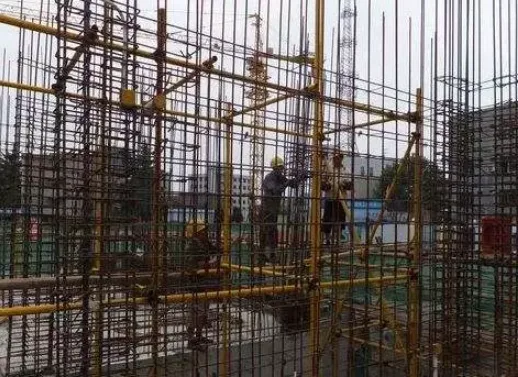
Reinforcement Positioning
1. Basic Raft Reinforcement Positioning
To ensure the effective thickness of the raft foundation, additional erection reinforcement should be added when binding the raft reinforcement. This method involves placing transverse reinforcement at 1500mm intervals along the longitudinal direction of the raft, and vertical reinforcement with slant supports welded to the transverse bars spaced at 1000mm transversely. The reinforcement diameter matches that of the raft reinforcement.
2. Reinforcement Positioning for Basement Waterproofing Plate
To maintain the effective height of the steel mesh layers in the waterproof plate, horse stool steel bars are used as supports. Their height is calculated based on the thickness of the bottom plate and the protective layer thickness of the steel bars. Horse stools are arranged with 1000mm vertical and horizontal spacing. The material is HRB400 Φ14 steel bars, with height equal to the water-resistant plate height minus the upper protective layer and bar diameter.
3. Column Reinforcement Positioning Bars
Hidden column reinforcement is secured with horizontal positioning stirrups, while wall reinforcement uses positioning ladder bars fixed to slab reinforcement to prevent displacement and ensure the protective layer thickness.
For frame columns, positioning bars are added where column dowels meet the base plates, tied firmly to prevent displacement. At cross-section changes, bending points must meet design specifications. To ensure consistent spacing of main column bars, a special 14mm diameter positioning hoop is tied atop the column before installing hoop bars.
4. Wall Reinforcement Positioning
Shear wall bar spacing is controlled by vertical and horizontal steel ladders, along with horizontal limit top bars. Vertical steel ladders use bars one size larger than the wall’s vertical bars, replacing them. Horizontal steel ladders are placed at template upper openings, with hooked ends to clamp vertical bars and secure their position. The horizontal limit top bars control template spacing and feature smooth contact surfaces, processed with a toothless saw.
5. Main Building Floor Reinforcement Positioning
To prevent crushing and stepping damage to the floor slab’s upper reinforcement, and to ensure the placement of negative reinforcement and protective concrete layer thickness, all floor reinforcement is supported by finished horse stool reinforcement. The stool height is calculated from slab thickness minus the protective layers and bar diameters. The main reinforcement bars of the stool are 6.5mm in diameter, with 4mm diameter legs, spaced every 1000mm both longitudinally and transversely.
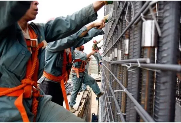
Installation of Steel Bars for Foundations and Main Structures
Rebar Installation
(1) Mechanical Connections: When installing mechanical couplers onsite, first place the sleeve on the fixed end of the rebar, then insert the other bar and tighten using a torque wrench. Post-installation, ensure equal thread exposure on both sleeve ends (generally 0–2 thread pitches), complying with JGJ 107-2016 standards.
(2) Overlap or Welded Bars: Electric slag pressure welds must meet these criteria: a minimum 4mm weld bead height, no burn defects at the electrode contact, bending angle under 3°, and axis offset within 0.1 times the bar diameter or 2mm.
(3) Prestressed Bars: These should be installed per the model, spacing, protective layer thickness, and other specifications outlined in drawings or codes.
(4) Additional Reinforcement: For walls built on slabs, reinforcing bars must be added at the slab bottom beneath the wall unless otherwise noted. For slab spans (L) less than 1500mm, use 2 bars of 12mm diameter; for spans between 1500mm and 2500mm, use 3 bars of 12mm; for spans equal or greater than 2500mm, use 3 bars of 14mm anchored at supports. Additional reinforcement should also be applied at raft external corners as specified.
Installation of Water Stop Steel Plates
Water stop steel plates must be installed as per design drawings. Connections should be fully welded with attention to welding current to avoid steel plate damage. After welding, slag must be removed, weld quality inspected, and any defects such as porosity fixed promptly.
Construction Quality Requirements
1. Control of Steel Reinforcement Protective Layer
To address common issues like steel displacement and uneven concrete protective layer thickness, the project uses steel bar spacing frames at wall and column openings during structural construction. Specialized positioning clips, replacing traditional mortar pads, ensure steel bar stability and protective layer accuracy. Positioning bars are installed at bases and openings of walls and columns to maintain correct dimensions. Under roof areas, new cylindrical cushion blocks offer higher strength, better stability, and cost efficiency compared to traditional materials.
2. Quality Control of Steel Bar Binding
(1) Joint Position, Overlap, and Anchorage Length: Steel bar joints must be properly spaced and staggered. Lap and anchorage lengths must meet minimum design and construction code requirements. Mechanical connection joints should be staggered, with connection lengths of 35 times the bar diameter. In high-stress zones, longitudinal tensile bar joint area should not exceed 50%, and joints are prohibited in seismic reinforcement zones unless equivalent strength and quality are ensured.
(2) Installation Position Tolerances and Inspection: After tying, steel bars undergo strict inspection per quality standards. The three-inspection system applies, including weld joint performance testing and ensuring all connections meet design requirements. Prefabricated components are also inspected accordingly.
Prevention and Control of Six Common Quality Issues
1. Displacement of Main Reinforcement in Columns and Walls
(1) Custom mold-type positioning stirrups are fabricated per column cross-section and reinforcement specs, placed at column heads and firmly tied to control bar position and protective layer thickness.
(2) After binding hidden column reinforcement, positioning stirrups are added atop the column and removed after concrete pouring.
(3) To ensure wall reinforcement alignment, a horizontal ladder reinforcement is installed 200mm above the slab before concrete pouring to position vertical bars. This ladder does not replace horizontal reinforcement.
(4) Wall horizontal reinforcement is controlled by vertical trapezoidal positioning bars, with at least one bar per wall and one every 5 meters for long walls. Steel reinforcement skeletons elsewhere are secured with embedded iron wire pads as per regulations. Anti-rust paint is applied at ladder reinforcement ends to prevent rust stains during putty application.
2. Reinforcement Loosening and Detachment
(1) The “eight-character” tying method is strictly used, with cross buckles securing prone-to-loosen areas. Binding wire must be at least double-stranded and firmly tied. Finished products should be protected from impact.
(2) Within lap lengths, centers and ends must be securely tied. Intersections of bidirectional bars require full binding without skipped ties. Bars under 12mm use No. 22 lead wire; 14mm and 16mm bars use No. 20; bars 18mm and above use double No. 22 lead wire.
3. Protective Layer Thickness Out of Tolerance or Exposed Reinforcement
(1) Protective layer thickness is measured from the outer edge of the outermost reinforcement, including hoops and distribution bars. Cushion block thickness for beams and slabs must conform to design requirements. Cushion blocks must be uniform and standard types only.
(2) Cushion blocks must be firmly fixed: minimum M20 strength, 40x40mm size, spaced no more than 1m apart, with 18-gauge binding wires reserved. Plastic blocks must meet strength standards and be tied securely. Crushed stone or marble blocks are prohibited.
(3) Before concrete pouring, steel bars must be securely fixed; construction channels and platforms should be provided for personnel. Walking on steel bars is forbidden. Vibration rods must not contact steel frames or cushion blocks indiscriminately.
(4) For concrete components requiring bottom insulation (e.g., basement ceilings), insulation boards must not be placed directly on formwork. Post-bonded insulation methods ensure protective layer thickness compliance.
4. Excessive Spacing Between Multiple Rows of Longitudinal Bars on Beams
(1) Use short bars of at least 25mm diameter as spacers to maintain clear distances between upper and lower rows of beam longitudinal bars per design and code.
(2) Spacer bars must be tightly secured with cross buckles. Initial spacers on beam top are placed 0.5m from supports and every 3m mid-span; bottom spacers are at 1.5m from supports and every 3m mid-span. At beam intersections or where bars cross, spacers are not required.
5. Steel Bar Positioning at Primary and Secondary Beam Nodes Outside Tolerances
(1) Construction teams must prepare detailed 2D or 3D drawings of main/secondary beams, beam-column nodes, and reinforcement layout, ensuring logical binding sequences. Based on actual cross-sections, binding plans for main and hoop bars at intersections are developed and followed.
(2) Stirrup density at main-secondary beam junctions is increased per design; typically, three extra stirrups at 50mm spacing for main beams.
(3) When binding steel bars in core beam-column areas, first insert bottom beam bars, then bind column stirrups, finally insert upper beam bars.
(4) If the frame beam aligns flush with the column side without design specs, place column main reinforcement outside and beam main reinforcement inside. Outer longitudinal beam bars may bend gently into the column at a 1:12 slope, adjusting beam hoop reinforcement accordingly. When edge beam concrete cover exceeds 40mm, add 12mm structural reinforcement to prevent cracking.
(5) Column stirrups in beam-column core areas should be densified as required, calculating stirrup counts to avoid omissions in prefabrication.
6. Protective Layer Thickness of Upper Reinforcement in Cast-in-Place Floor Slabs Exceeds Tolerance
(1) Steel bar stools must be used to stably support upper layer bars, ensuring position and protective layer thickness. Stool size, quantity, and spacing are defined in construction plans based on protective layer thickness and bar diameter. For thicker slabs or transfer floors, stool parameters must be calculated to meet strength and stiffness requirements, typically spacing not exceeding 1m.
(2) Upper steel bars must be firmly tied to distribution bars to form a stable reinforcement cage, preventing displacement. Anti-floating measures should be implemented for cast-in-place hollow slabs.
(3) Prior to concrete pouring, construction channels separated from negative moment reinforcement must be set up as per plans. Personnel are strictly prohibited from stepping on reinforcement or placing equipment on it.
(4) Before tying, templates should be pre-inspected. Control lines are snapped along template lengths for reference. Cross buckles are used for tying, with fine adjustments made after each section to correct deviations.
Article source: Architectural Technology Magazine


Must log in before commenting!
Sign Up