1
BIM (Building Information Modeling) creates a digital, virtual representation of a building. Its primary goal is to accurately reflect each building component and its associated information. However, due to software implementation constraints, it is not always possible to fully model the real-life classification, composition, and connection relationships between components. Built-in rules are therefore necessary to make the model as realistic as possible while keeping the modeling process straightforward. Additionally, the level of detail can be adjusted according to project stage and purpose, while also meeting requirements for data exchange and collaborative design across various platforms.
Currently, mainstream BIM modeling software—such as Autodesk Revit 2013 and Graphisoft ArchiCAD 15—structures its framework around common building elements: walls, doors, windows, columns, beams, floors, stairs, roofs, etc. Over multiple versions, these systems have matured, yet some limitations persist in practice. This article focuses on the logical relationship between the core component and its attachment layers.
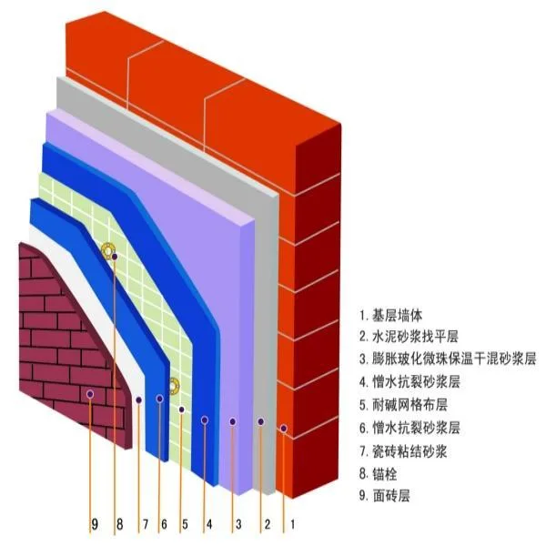
In real-world construction, categories like walls, columns, beams, floors, and roofs often require a decorative layer outside the main structure, and sometimes a filling layer between the core and decorative layers. Since both the decorative and filling layers are attached to the component’s main body, this article defines the main structural layer as the “core layer,” and collectively refers to the decorative and filling layers as the “attachment layer.” As illustrated in Figure 1, the schematic of a typical insulation mortar wall shows the base wall as the core, with multiple attachment layers outside it.
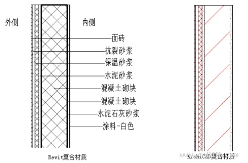
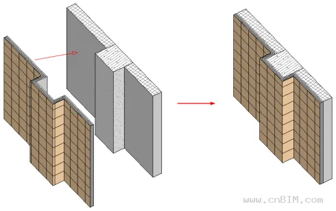
Mainstream BIM software currently treats the attachment layer as a logical extension of the main component, achieved technically by using “composite materials.” Figure 2 demonstrates how Revit and ArchiCAD simulate an insulated wall using composite materials.
While composite materials solve the basic modeling of walls, floors, and roofs, there are still two categories—beams and columns—for which the software offers limited solutions. Moreover, applying composite materials in BIM practice presents several challenges. The following sections summarize and analyze these issues.
II
1
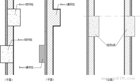
A primary issue is the inability to apply attachment layers to beam and column components. For exterior beams and columns, the outer attachment layer typically matches the exterior wall finish; for interior beams and columns, the finish aligns with the interior walls. Current versions of Revit and ArchiCAD handle these layers differently:
1)
2)
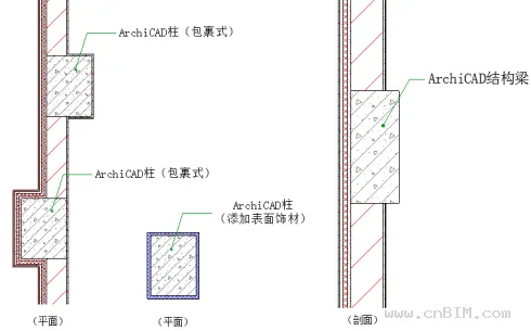
In practice, column decorative layers can be managed—even in Revit—by manually adding a wall layer. For beams, there is no straightforward solution unless customizing the section.
2
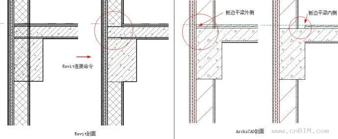
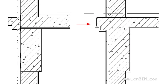
At junctions between walls, columns, beams, and slabs, attachment layer connections are complex and often do not correctly align with the core structure. Both Revit and ArchiCAD attempt to address this, but the results are unsatisfactory. Figure 5 highlights the common issue where walls intersect with slabs or beams.
3
In structural engineering, only the core layer is typically relevant. When exporting BIM models to structural analysis software, components with composite structures may lead to misinterpretation—for example, the core size being mistaken for the total thickness including attachments. When importing Revit or ArchiCAD models into Tekla Structure via IFC, all components may be displayed with their total thickness, causing errors in collaborative workflows.
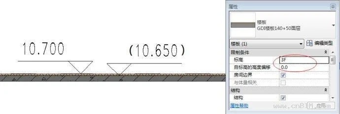
Even within Revit’s architectural and structural disciplines, using worksets for collaboration can result in confusion or conflicts. For example, as shown in Figure 6, the architectural elevation for a floor slab may be 10.700, but the structural elevation is 10.650. Because there is no parameter linking the core layer’s elevation, this discrepancy leads to misalignment between architectural and structural models. If only the core layer is modeled for structure, the architectural attachment and filling layers cannot be represented—highlighting a contradiction between disciplines.
4
Revit allows control over model detail via “Detail Level,” but cannot display only the core layer, and this setting does not affect 3D views. ArchiCAD’s “Partial Structure Display” can toggle depth, but since the attachment layer is always part of the component and cannot be separated, downstream applications also keep them combined. In reality, core, filling, and decorative layers are constructed separately. When importing models to Navisworks for 4D construction simulation, it is difficult to independently simulate these processes.
5
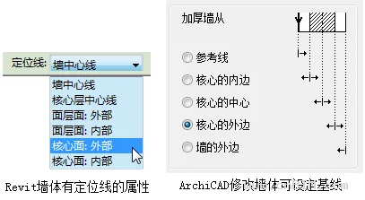
As design develops, changes in component materials are common. For walls, current BIM software allows various positioning methods (see Figure 7). For example, using the outer edge of the core layer as a reference ensures changes to insulation or decorative finishes do not shift the core structure.
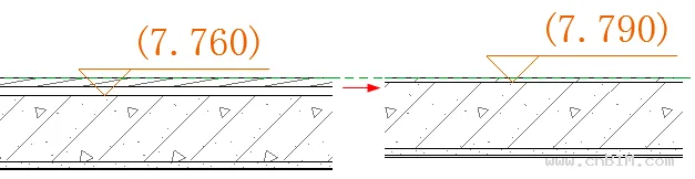
Other components, such as floors and roofs, do not receive such treatment. Their positioning is overall—floors at the top, roofs at the bottom. Changing the finish (e.g., from wooden floor to tile) alters the structural elevation, as in Figure 8. This is not consistent with real-world practice and can create significant issues in multidisciplinary collaboration.
In renovation, the filling and decorative layers should be freely replaceable, while the core structure should remain fixed. However, in current BIM software, changing the floor material requires manually adjusting elevations to maintain the core structure’s position, which may trigger a series of further adjustments.
6
Due to these software limitations, detailed design often requires manual 2D corrections for attachment layer junctions (see Figure 9). This process is time-consuming and reduces BIM design efficiency, discouraging designers.
III
The core issue stems from treating the attachment and core layers as inseparable and independent for each component, without holistic consideration. To address this, software vendors could refine component settings, enhance connections between elements, and optimize attachment layer handling—especially for IFC format conversion.
However, rethinking the conventional approach of modeling each component type separately, and reconsidering the relationship between attachment and core layers, may offer new perspectives. In reality, the attachment is not always a fixed part of the core—construction processes differ significantly. For example, “bare shell” and “fully decorated” rooms have different construction sequences: the core layer should exist independently, while the attachment layer can be added, removed, or replaced at any time without affecting the core.
Based on this, the author proposes introducing a separate “Attachment Layer” entity. Without considering implementation difficulties, the following technical features are suggested:
1)
2)
3)
If adopted, these measures would resolve the aforementioned problems.
4
1
Independent attachment layers can be applied to various components—walls, columns, beams, slabs, even stairs—as shown in Figure 10.
2
With this approach, attachment layers of the same material automatically connect, so only the main component junctions need attention. Attachment layers can be seamlessly applied, as seen in Figure 11.
3
Separating attachment layers from the core allows each discipline to focus on relevant aspects. For instance, structural and architectural teams can coordinate floor elevations without conflict, as attachment layers are managed independently.
4
Attachment layers can be toggled on or off as needed, supporting various project phases and disciplines. In 4D simulations, construction of attachment layers can be scheduled separately, and material quantities are easier to manage.
5
Crucially, separating the layers allows adjustments to attachment material or thickness without impacting the core’s position—especially important for renovation projects.
6
As seen in Figure 11, such a modeling approach eliminates the need for additional manual drawing, improving efficiency.
5
As BIM technology advances, software limitations become more apparent, highlighting the need for further communication and improvement between vendors and users. The current approach to component and attachment layer relationships is inconvenient for practical applications. Therefore, this article proposes a bold solution: separate the attachment layer from the main body, making it an independent component to resolve a range of issues. Whether this approach is technically feasible, or introduces new challenges, requires further exploration.


Must log in before commenting!
Sign Up