Introduction
Architectural structures with unusual shapes can face serious risks and consequences if minor displacements occur during construction. However, these displacements can be effectively prevented by following proper measures. Let’s explore these prevention methods together.
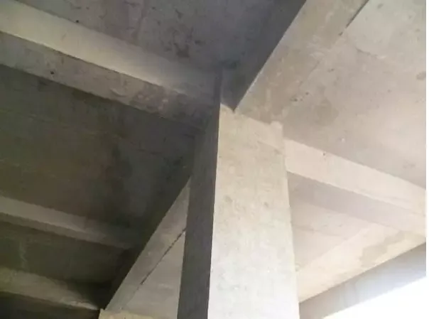
Wall Beam Column Axis Displacement
Consequences
This displacement affects the building’s structural stress distribution and reduces the effective usable area.
Design Measures
During the design phase, reduce the variety of component cross-sectional dimensions and arrange components as closely as possible along the main axis.
Material Selection
(1) Choose formwork templates from reputable manufacturers, ensuring they are square, flat, and exhibit excellent strength, rigidity, wear resistance, and minimal deformation when exposed to water.
(2) The materials used for the main and secondary keels and support frames in the formwork reinforcement must meet engineering requirements and comply with national standards.
Construction Measures
(1) Concrete pouring exerts significant force on shear and mountain walls, potentially causing displacement between the east and west mountain walls. To prevent this, reinforce the formwork support system with diagonal braces and steel wire ropes.
(2) Fill the gap between the pump pipe riser and the reserved hole in the concrete floor slab with square wood and waste tire rubber pads. Embed prefabricated fixing rings on the poured floor slab and orient them opposite to the pump’s sitting force. The steel wire rope should form a 60° angle with the floor slab, securing the pump pipe to reduce vibration. Ensure sufficient clearance between the pump pipe and floor formwork during pouring to avoid contact.
(3) Before installing formwork, mark the axis lines and column edges on the ground. When supporting the formwork, erect column formwork at both ends, align and check verticality by pulling a line across the top, then support intermediate columns. For closely spaced columns, install horizontal crossbars and diagonal braces; for wider spacing, support each column on all four sides to maintain verticality and alignment.
(4) Use highly accurate laser plumb or laser theodolite instruments, along with steel rulers and tape measures that meet standards and have passed metrological verification. Maintain and calibrate these instruments regularly during construction.
(5) Design the position of payoff holes according to the actual engineering situation, choosing appropriate methods to ensure vertical alignment of base payoff holes. When projecting axis control points internally, use ground floor control points as references when possible. Use the building’s edge axis as the control line, avoiding vertical components like frame columns and shear walls. Typically, place the axis control line 1000mm from the axis, adding a middle line for large plans. Set payoff holes (150mm x 150mm) at intersections and use plumb bobs and theodolites to verify accuracy. After measurements, conduct re-verification and inspections by quality technicians and supervising engineers.
(6) Positioning bars should be set on both sides of shear walls and frame columns. Snap boundary lines and implant 14mm diameter positioning steel bars spaced 800mm apart, 200mm in length, flush with the wall’s outer surface. Drill holes 16mm in diameter and 80mm deep into the cast-in-place slab to insert the bars, driving them in with a hammer and coating with anti-rust paint. Snap control lines 200mm on both sides of the shear wall edge to control wall axis alignment and formwork placement.
Management Measures
After concrete pouring and before initial setting, quality controllers and surveyors must immediately review the structural components’ axis positions against control lines. Any displacement found should be corrected promptly.
Key Quality Control Points
(1) Construction personnel must carefully control measurement accuracy during positioning and layout, strictly following review and inspection procedures.
(2) Materials such as formwork, supports, tension rods, and steel wire ropes should undergo qualified on-site acceptance.
(3) Construction must strictly comply with the approved special formwork engineering plan.
(4) After formwork support installation, check and accept according to the plan.
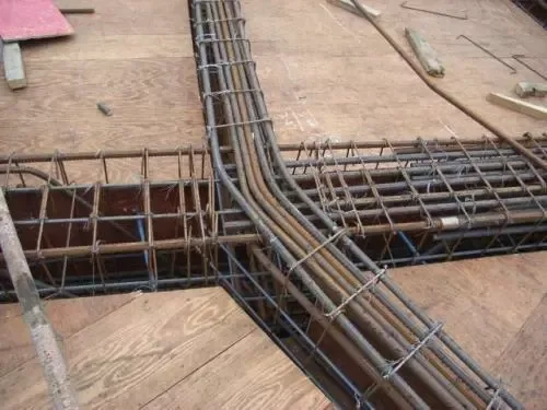
Reinforcement Displacement
Consequences
Reinforcement displacement reduces the bearing capacity of concrete bending members, increases crack width and deformation, and affects temperature-induced cracking.
Main Reinforcement of Shear Wall Reinforced Columns
(1) To prevent horizontal reinforcement displacement, ensure spacing and positioning meet design and specifications. Horizontal reinforcement must be firmly tied or welded, and stepping on it during binding is strictly prohibited.
(2) To prevent vertical reinforcement displacement, add temporary positioning hoops at 5cm and 50cm from the concrete surface root, firmly tied or welded. Assign personnel to supervise reinforcement during concrete pouring and correct displacement immediately.
(3) For column main reinforcement, add temporary positioning hoops at 5cm and 50cm from the concrete surface root, firmly tied or welded. Supervise steel reinforcement during pouring and correct any displacement promptly.
(4) Position the pumped concrete outlet between steel bars; do not direct it straight at the bars.
(5) When vibrating concrete, avoid contact between the vibrator rod and steel bars. Steel bar supervisors must monitor and immediately correct any displacement. Manual stepping or twisting of steel bars is strictly forbidden.
Handling Displacement of Main Reinforcement in Shear Wall Reinforced Columns
(1) For steel bars displaced within 2cm outside the template line, chisel a small pit about 5cm deep at the steel bar root. Bend and adjust the bars inside the template line with a wrench, ensuring a bending ratio of at least 1:6. Heat treatment for bending is forbidden.
(2) For steel bars displaced more than 2cm outside the template line, similarly chisel a 5cm deep pit, bend and adjust the bars inside the template line with a wrench, maintaining the bending ratio of 1:6. Avoid heat treatment and add reinforcement steel bars at the bending point on both sides according to anchorage length.
(3) For steel bars displaced within the template line, bend and adjust them and add reinforcement bars at the bending points to meet anchoring requirements, tying and overlapping one steel bar.
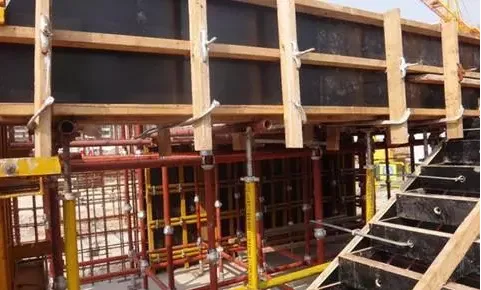
Template Displacement
Consequences
Displacement of wall and column formwork causes axis displacement immediately after concrete pouring. This can prevent masonry walls from properly bonding with displaced concrete walls during secondary structural construction, which cannot be corrected later. In residential buildings, severe formwork axis displacement can significantly reduce the effective living area.
Preventive Measures
(1) Follow detailed drawings at scales of 1:15 to 1:10, showing part numbers, axis positions, dimensions, section shapes, reserved holes, and embedded parts. Conduct technical reviews and disclose details to the production team and operators as the basis for template production and installation.
(2) After measuring and laying out the formwork axis, organize technical review and acceptance by a dedicated person. Only proceed with formwork support after confirming accuracy.
(3) Implement reliable limiting measures at the base and prefabricated parts of wall and column formwork, such as embedding short steel bars in cast-in-place floor concrete to fix steel supports, ensuring accurate bottom positioning.
(4) Draw horizontal and vertical lines when supporting formwork, and set verticality control lines to guarantee precise positioning.
(5) Design building templates specifically according to concrete structure characteristics, ensuring adequate strength, stiffness, and stability of templates and supports.
(6) Before pouring concrete, thoroughly inspect and review the axis, supports, top braces, and bolts of the formwork, addressing any issues immediately.
(7) During concrete pouring, distribute material evenly and symmetrically, and strictly control pouring height within specification limits.
Article source: Architectural Technology Magazine


Must log in before commenting!
Sign Up