1. During the construction drawing design phase, the structural design documents should include a comprehensive list of drawings, design specifications, design drawings, and calculation sheets.
2. The drawing catalog must be organized by drawing number, with newly created drawings listed first, followed by selected reusable and standard drawings.
General Description of Structural Design
For each project, a general structural design specification should be prepared. For projects comprising multiple sub-projects, a unified general structural design specification must be developed.
If the project primarily involves steel structures or contains a significant number of steel components, a dedicated general specification for steel structure design is required. For simpler projects, the general description can be included separately within the relevant drawings.
The general description of structural design should cover the following aspects:
1. Project Overview
1) Location of the project, surrounding environment (such as rail transit), zoning, and primary functions;
2) Dimensions of each building or partitioned section—including length, width, height, number of floors above and below ground, floor heights, structural type and regularity, main structural spans, special structures or shapes, and crane capacities in industrial plants;
3) If prefabricated structures are used, specify the type of structure and the prefabricated components involved.
2. Design Basis
1) Design service life of the main structure;
2) Natural conditions: basic wind pressure, ground roughness, basic snow pressure, temperature (if applicable), seismic fortification intensity, etc.;
3) Engineering geological survey report;
4) Site seismic safety assessment report (if necessary);
5) Wind tunnel test report (if applicable);
6) Relevant node and component test reports (if required);
7) Vibration table test report (if applicable);
8) Written structural requirements proposed by the construction unit, compliant with relevant standards and regulations;
9) Review and approval documents for preliminary design;
10) For high-rise buildings exceeding limits, an approval document for the feasibility study report of the over-limit structural design is required;
11) For pile foundations, bearing capacity must be tested according to relevant specifications, with test reports provided;
12) List of key regulations and standards adopted in the design, including names, numbers, publication years, and version numbers.
3. Drawing Instructions
1) Units used for elevations and dimensions in the drawings;
2) Absolute elevation value corresponding to the design elevation of 0.000m;
3) Description of drawing numbering if organized by engineering zones;
4) Codes for common components and instructions for component numbering;
5) Description of steel bar codes, section steel codes, and section size markings;
6) When using planar integral representation for concrete structures, indicate the name and number of the standard drawing used or provide the standard drawing.
4. Building Classification Levels
Explain the following building classification levels and their governing specifications or approvals:
1) Safety level of the building structure;
2) Foundation design grade;
3) Seismic fortification classification for buildings;
4) Main structure type and seismic grade;
5) Groundwater level elevation and basement waterproofing grade;
6) Design categories, civil air defense basement resistance levels against conventional and nuclear weapons;
7) Fire protection classification and fire resistance levels;
8) Environmental category of concrete components;
9) Classification of buildings on collapsible loess sites;
10) For over-limit buildings, specify seismic performance objectives and levels for the structure and components.
5. Main Load (Action) Values and Design Parameters
1) Loads from building surface layers and suspended ceilings;
2) Wall loads and special equipment loads;
3) Railing loads;
4) Live loads on floors and roofs;
5) Wind loads, including ground roughness, shape coefficients, and wind-induced vibration coefficients;
6) Snow loads, including distribution coefficients;
7) Seismic actions, covering design basic seismic acceleration, grouping, site category and characteristics, damping ratio, and maximum horizontal seismic influence coefficient;
8) Design parameters related to temperature effects and basement water buoyancy.
6. Design Calculation Program
1) Provide the program name, version number, and developer used for overall structural and other calculations;
2) Describe the calculation model for structural analysis, including embedded parts and bottom reinforcement zones for multi-story and high-rise buildings.
7. Main Structural Materials
1) Performance indicators of structural materials;
2) Concrete strength grades (by elevation and location), impermeability grades for waterproof concrete, density grades for lightweight aggregate concrete; specify durability requirements and use of pre-mixed concrete;
3) Types and strength grades of masonry, mortar types and quality control levels, as well as pre-mixed mortar requirements;
4) Types and locations of steel bars, steel strands or high-strength wires, applicable product standards, and special requirements (e.g., strength-to-yield ratio);
5) Technical parameters for finished cables, prestressed structure anchorages, finished bearings (rubber, steel, seismic isolation bearings), dampers, and other specialized products;
6) Materials used for steel structures as specified in Article 4.4.3, Clause 10;
7) Types and requirements for prefabricated structural connection materials, including sleeves, anchor metal corrugated pipes, cold extrusion joints, tension components, grout materials, bolts, joint materials, and other connection materials.
8. Foundation and Basement Engineering
1) Overview of engineering geology and hydrogeology, soil compression modulus, bearing capacity characteristics, treatment for poor foundations, anti-liquefaction measures, freezing depth, and special geological conditions;
2) Indicate foundation type and bearing layer; for pile foundations, specify pile type, diameter, length, bearing layer, and penetration depth. Include characteristic values for single pile bearing capacity (vertical tensile and horizontal if applicable), and foundation bearing capacity testing requirements;
3) Design water level and anti-floating measures for basement waterproofing, construction precipitation requirements, and cessation conditions;
4) Backfilling requirements for foundation and abutment pits;
5) Construction requirements for large-volume concrete foundations;
6) Define boundaries between civil defense and non-defense areas in civil defense basements;
7) Testing requirements for various foundation types.
9. Reinforced Concrete Engineering
1) Environmental categories of concrete components and protective layer thickness for outer steel bars;
2) Reinforcement anchorage and overlap lengths, connection methods, and anchorage requirements for components;
3) Methods and layout for ducts and grouting in post-tensioned prestressed components; construction requirements for tensioning and anchoring ends, and anchor protection;
4) Tensioning control stress, sequence, conditions (e.g., concrete strength), and necessary testing for prestressed structures;
5) Requirements for beam and slab arching and demolding;
6) Construction requirements for post-pouring strips or blocks, including timing for supplementary pouring;
7) Location and treatment of construction joints for special components;
8) Unified requirements for reserved holes and embedded parts, including reinforcement;
9) Lightning protection grounding requirements.
10. Steel Structure Engineering
1) Overview of parts, structural forms, and main spans of steel structures;
2) Steel materials: grades, quality levels, and product standards; specify physical, mechanical, chemical properties, Z-direction performance, carbon equivalent, weather resistance, delivery status if necessary;
3) Welding methods and materials for different steel types;
4) Bolt materials: type, performance level, surface treatment for high-strength bolts, friction coefficients, and product standards;
5) Types and standards for welding nails;
6) Steel component forming methods (hot rolling, welding, cold bending/pressing, hot bending, casting), and types of round steel pipes (seamless, welded);
7) Cross-sectional forms and product standards for profiled steel plates;
8) Weld quality grades and inspection requirements;
9) Production requirements for steel components;
10) Installation requirements for steel structures, including arching for large-span components;
11) Painting requirements: rust removal method and grade, anti-corrosion primer type, minimum dry film thickness, intermediate and topcoat specifications, fire resistance limits, fireproof coating types, anti-corrosion periods, and maintenance;
12) Connection requirements between steel structure main body and enclosure structures;
13) Structural inspection and testing requirements for special nodes if necessary.
11. Masonry Works
1) Material type, thickness, and weight limits for completed masonry walls;
2) Connection requirements between masonry infill walls and frame beams, columns, or shear walls, or reference to standard drawings;
3) Lintel requirements for door and window openings or reference to standard drawings;
4) Requirements and references for construction columns and ring beams (tension beams).
12. Testing and Observation Requirements
1) Settlement observation requirements;
2) Health monitoring during inspection, construction, and use of large-span and special structures;
3) For high-rise and super high-rise buildings, additional deformation observations such as sunlight deformation as applicable;
4) Foundation pile testing.
13. Construction Precautions
If foundation pits are involved, technical design requirements for the pits must be specified.
For projects following green building standards, a green building design specification should be included.
1) Explain building shape classification regularity according to the “Code for Seismic Design of Buildings” (GB50011).
2) Clarify the scope and dosage ratio of reusable and recyclable materials used in design—such as pre-mixed concrete and mortar, steel bar selection principles, high-strength materials, and prefabricated components.
For projects with prefabricated structures, special instructions should cover:
1) Design basis and supporting drawings:
① Main regulations and standards applied for prefabricated structures, including names, numbers, years, and versions;
② Supporting atlases with corresponding details;
③ Materials and performance requirements;
④ Detailed and processing drawings of prefabricated components.
2) Production and inspection requirements for prefabricated components.
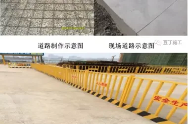
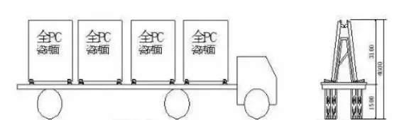
3) Transportation and stacking requirements.
4) On-site installation requirements.
5) Acceptance criteria for prefabricated structures.
4. Basic Floor Plan
1) Draw the positioning axis and indicate position, size, bottom elevation, and component numbers for foundation elements (bearing platforms, foundation beams, etc.). If bottom elevations vary, include slope diagrams. Indicate locations and widths of pouring strips post-construction.
2) Specify positions, sizes, and numbers of masonry walls, piers, and columns. Concrete structures may include separate plans for structural walls and columns, with cross-sectional dimension changes noted.
3) Indicate plan positions, sizes, and elevations of trenches, pits, and equipment foundations, along with locations, sizes, and elevations of reserved holes and embedded parts.
For settlement observation, indicate observation point locations, preferably with detailed measurement point drawings.
The basic design description should include foundation bearing layers, depth of foundation penetration, characteristic bearing capacity values, inspection requirements, backfill treatment, and construction notes.
For pile foundations, draw pile locations, positioning dimensions, and pile numbers. For test piles, provide separate positioning plans.
For artificial composite foundations, illustrate treatment range and depth, layout, material and performance requirements, and detailed drawings for replacement piles. Specify bearing capacity characteristic and deformation control values, along with testing requirements.
When designed by a qualified unit, the foundation designer must specify bearing capacity, deformation control values, and corresponding testing requirements.
5. Basic Detailed Drawing
1) Draw sections, foundation ring beams, and moisture-proof layer positions for unreinforced extended masonry foundations, indicating overall and sub-dimensions, elevations, and positioning.
2) For expanded foundations, include plans, sections, reinforcement, and foundation cushion layers with all relevant dimensions and elevations.
3) Provide detailed drawings of pile foundations, pier caps, and pile-to-pier cap connections, including pile top elevation, length, cross-section, reinforcement, and joint details for prefabricated piles. Include geological overview, bearing layers, construction requirements, testing, and characteristic bearing capacity values. For test piles, provide separate detailed drawings and requirements. Bearing platforms should have plans, sections, cushion layers, reinforcement, and dimension details.
Raft and box foundations may be represented by atlases, but load-bearing wall and column positions must be shown. Indicate post-pouring strip locations and provide detailed construction drawings when required. For basement foundations, show plans, sections, and reinforcement for concrete walls. If reserved holes, embedded parts, or complex structures are numerous, a separate wall template diagram may be drawn.
Foundation beams may be represented according to standard atlases.
Note: For simple, regular unreinforced extended foundations, beams, and pier slabs, list methods may be used.
6. Structural Plan
The general building structural plan should include floor plans for each level and the roof structure plan (see Article 10 for steel structure plan requirements). Specific content includes:
1) Draw positioning axes and locations of beams, columns, load-bearing walls, seismic structural columns, with necessary dimensions, numbering, and floor elevations;
2) For prefabricated wall and column structures, use different fill symbols to distinguish prefabricated and cast-in-place components; indicate component numbers, model relationships, detailed drawing references, panel spans, quantities, bottom elevations, and reserved hole sizes and locations; show prefabricated beams, portal beams, and beam elevations;
3) Cast-in-place slabs should show thickness, surface elevation, reinforcement (optionally with enlarged or separate reinforcement templates), local sections at elevation or thickness changes, reserved holes, embedded parts, equipment foundations, and required reinforcement at hole edges; indicate pouring strip positions post-construction; elevator machine rooms should show position and detailed hook drawings;
4) For masonry with ring beams, indicate position, number, and elevation; a simple plan on a small scale is acceptable;
5) Stairwells can be marked with diagonal lines, numbering, and detailed drawing references;
6) Roof structure plans should mirror floor plans, marking slopes, directions, elevations at slope start and end points, roof openings, facility positions and sizes, and detailed drawings; parapet walls or structural columns should be identified by position, number, and drawing references;
7) When using standard drawing nodes or additional nodes, indicate detailed drawing index numbers in the plan;
8) Civil air defense basement plans should identify civil defense and non-defense areas and specify civil defense wall types and numbers.
For single-story open buildings, component layout and roof structure plans should include:
1) Component arrangements with positioning axes, layout, numbering, elevations, and detailed drawing references for walls, columns, lintels, door frames, canopies, supports, and beams, with explanations; sectional and vertical layouts as needed;
2) Roof structure layout showing positioning axes, component positions and numbers, support system layout, reserved hole positions and sizes, detailed node drawing index numbers, and explanations.
7. Detailed Drawing of Reinforced Concrete Components
1) Cast-in-place components (beams, slabs, columns, walls, etc.) should include:
1) Longitudinal profiles showing length, positioning, elevation, reinforcement, and supports (standard drawing profiles may be used); prestressed components require reinforcement positioning diagrams and anchoring/tensioning requirements;
2) Cross-sections with positioning, dimensions, and reinforcement (standard cross-section diagrams may be used);
3) Wall elevation drawings if necessary;
4) Separate drawings for complex steel bars;
5) Reserved holes and embedded parts affecting stress must be marked with location, size, elevation, edge reinforcement, and embedded part numbers;
6) Enlarged plans for curved or broken-line beams, with unfolded drawings if needed;
7) General cast-in-place beams, columns, and walls may use “overall plane representation”; for dense annotations, separate longitudinal and transverse beam drawings;
8) Additional explanations, especially for deviations from standard drawings (e.g., steel bar anchorage, structural requirements);
9) Detailed connection or anchorage drawings for non-structural components and auxiliary mechanical/electrical equipment.
Note: Seismic design of non-structural components is the responsibility of relevant professionals.
2) Prefabricated components should include:
1) Component template drawings showing dimensions, reserved holes, embedded parts, elevations; for post-tensioned components, include duct positioning, tensioning, and anchoring ends;
2) Reinforcement diagrams showing longitudinal steel form, hoop diameter and spacing; separate non-prestressed reinforcement if complex; cross-sections with dimensions, steel bar specifications, locations, and quantities;
3) Additional explanatory content as needed.
Note: Simple, regular cast-in-place or prefabricated components may be represented by lists if regulations are met.
8. Detailed Drawing of Concrete Structure Node Construction
For cast-in-place reinforced concrete structures, detailed node construction drawings should be prepared (referencing standard designs and general drawings).
For prefabricated structures, detailed node, beam, column, and wall anchorage drawings should indicate positioning relationships, component codes, connection materials, specifications, models, performance, additional steel bars or embedded parts, connection methods, installation, and post-pour concrete requirements.
Include any necessary additional explanations.
9. Other Drawings
1) Staircase diagrams: plan and section views of each staircase structure with dimensions, component codes, and elevations; detailed drawings of stair beams and slabs may use list methods;
2) Embedded parts: plans, side or section views indicating dimensions, specifications, models, performance, and welding requirements for steel and anchor bars;
3) Special structures and constructions (water tanks, chimneys, pipe racks, trenches, retaining walls, silos, large or specialized equipment foundations, work platforms, etc.) require separate drawings including plans, characteristic sections, reinforcement, positioning, size, elevation, material types, specifications, models, and performance.
10. Steel Structure Design and Construction Drawings
The design and construction drawings for steel structures must meet detailed design requirements for steel structure production. These detailed drawings are generally prepared by specialized fabrication units or qualified entities. The depth of design is determined by the fabricator. These drawings do not include detailed fabrication drawings.
Construction drawings should include:
1) General description of steel structure design: for projects with significant steel structures (including steel frames), prepare a separate general description covering steel-related content as in Article 4.4.3;
2) Basic plans and detailed drawings showing steel column positions and their connections to lower concrete components;
3) Structural layout plans (each floor and roof) indicating positioning, elevation, component positions (drawn with thick lines), component numbers, section types and dimensions, node detail drawing indexes; include purlin and wall beam layouts, key section diagrams, and space grid views with member numbers, section types, dimensions, and node details;
Detailed component and node drawings:
1) Simple steel beams and columns may use standardized detailed drawings and lists showing steel grades, dimensions, and specifications, plus connection node details (referencing standard drawings);
2) Lattice components should be shown in plan, section, elevation or unfolded elevation drawings (for curved parts), with positioning, dimensions, component models, node details, and connection information;
3) Node details must include connecting plate thickness and dimensions, welding seam requirements, bolt models and arrangements, and welding nail placements.
11. Calculation Sheets
1) Manual structural calculation books should include schematic diagrams of component layouts, calculations or explanations of load values; content must be complete and clear, with organized steps and reliable data references. Use calculation charts and indicate sources for uncommon formulas. Component numbers and results should align with drawings.
When using computer programs, specify the program name, code, version, and developer in the calculation book. The program must be approved or appraised. Computer results should be analyzed and verified. The input data, calculation model, geometrical and load diagrams, and outputs should be compiled into a comprehensive document.
When using prefabricated structural standard drawings or reusable drawings, conduct necessary calculations per atlas instructions and project specifics, including them in the calculation sheets.
All calculation sheets must be reviewed and signed by designers, proofreaders, and reviewers (including approvers if required) on the cover and archived as technical documents.
For green building projects, calculate the proportions of high-strength and high-durability structural materials used.
Article source: Dr. Jianyan


Must log in before commenting!
Sign Up