Part 1: Project Overview, Compilation Basis, and Project Features
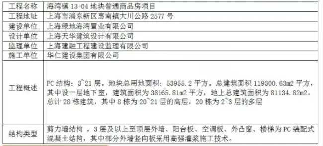
1.1 Project Overview
1.2 Compilation Basis
PC structural construction drawings and bidding documents.
GB 50068-2001: Unified Standard for Reliability Design of Building Structures.
GB 50009-2012: Load Code for Prefabricated R&D Building Structures.
GB 50010-2010: Code for Seismic Design of Buildings.
JGJ 3-2010: Technical Specification for Concrete Structures of Tall Buildings.
DG/TJ08-2069-2010: Code for Production, Construction and Quality Acceptance of Prefabricated Integral Residential Concrete Components.
1.3 Project Characteristics
1.3.1 Main Features
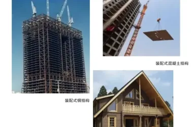
This project involves a prefabricated assembled concrete structure with the following key characteristics:
- On-site structural construction is carried out using prefabricated assembly methods, including finished components such as exterior wall panels, air conditioning panels, balconies, equipment platforms, protruding windows, and stairs.
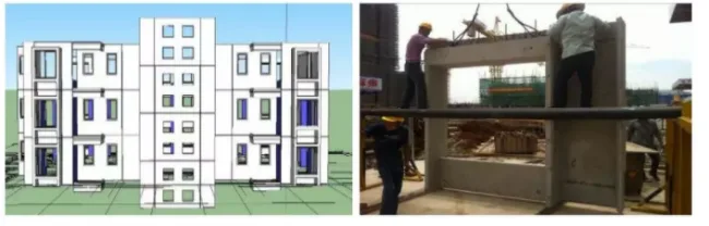
- Industrialized prefabrication: all components are manufactured on factory assembly lines and directly assembled on site.
- Design incorporates BIM technology to simulate component assembly and minimize installation conflicts. Some exterior wall PC structures use innovative sleeve reinforcement planting and high-strength grouting techniques to effectively connect PC components, improving utilization and construction efficiency.
- Stairs, balconies, and corridor railings are designed as PC components with embedded parts installed afterward.
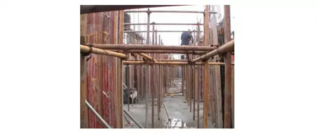
- Cantilevered external wall scaffolding is employed based on PC structure construction characteristics.
1.3.2 Waterproofing Features
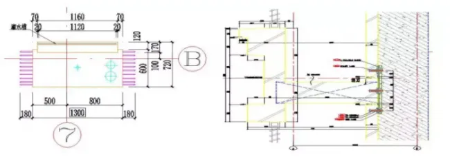
Node Self-Waterproofing: Waterproofing of prefabricated exterior wall panels is achieved through the following measures:
- Waterstop strips pre-applied on the sides and tops of panel walls to prevent water penetration.
- Waterproofing of cavity structures with grooves (troughs) for drainage between adjacent prefabricated exterior wall panels.
- Exterior sealing using weather-resistant waterproof adhesive on the prefabricated exterior wall panels.
1.3.3 Construction Characteristics
The critical aspects of PC structure construction in this project include:
- Factory production of prefabricated components.
- Lifting and on-site assembly of components.
- Temporary fixed connections.
- Selection of appropriate supporting machinery.
- Connections between prefabricated and cast-in-place structures.
- Waterproofing measures at nodes.
- Rubber strips and grouting procedures executed by skilled, multi-disciplinary construction teams.
1.3.4 New Engineering Technologies
This project incorporates new technological advancements including:
- High industrialization with resource conservation and environmental protection.
- Precision prefabrication and control at component factories.
- Alignment between detailed design drawings and on-site operability.
- Use of vertical lifting machinery matched to component dimensions.
- Temporary fixed connection methods and assembly error control.
- Enhanced waterproofing at prefabricated component joints.
- Strict construction process and technology control.
- Organization and training of professional multi-job construction labor.
- Innovative safety and product protection measures, including high-strength grouting technology, facilitating advancement in construction methods.
Part 2: Construction Deployment
2.1 Construction Preparation
2.1.1 Technical Preparation
Technical preparation is the cornerstone of construction readiness. Any technical errors or hidden risks may lead to serious safety incidents and quality defects, causing significant loss of life, property, and financial damage. The key technical preparation steps include:
- Familiarizing with and reviewing construction drawings and related design documents.
- Investigating and analyzing raw materials.
- Preparing the construction organization plan. Prior to construction, the project engineer convenes personnel from related departments to discuss drawings, resolve difficulties, and address onsite construction conflicts. Communication and coordination with the construction team, design unit, prefabrication factory, and other stakeholders are strengthened. Technical briefings are conducted in stages, tailored for different types of work, ensuring thorough implementation.
2.1.2 Material Preparation
Materials required for PC structure construction must be prepared before work begins to avoid delays and quality issues. The preparation process includes:
- Formulating material demand plans based on budgets, construction methods, and schedules.
- Organizing material sourcing, defining processing and supply logistics, and signing supply contracts.
- Planning transportation and storage schemes.
- Ensuring timely delivery and proper storage of materials on site in designated areas.
2.1.3 Labor Organization Preparation
Before construction, labor preparation includes establishing leadership structures, assembling an experienced and efficient construction team, organizing labor entry onsite, conducting technical disclosures, and setting up management systems.
Considering the complexity and quality demands of PC structure construction for this project, a dedicated PC structure construction team will be formed. This team will consist of approximately 30 members, divided into a PC structure construction team of 10 people and a grouting team of 2 people per building, to ensure specialized and efficient execution.
2.1.4 On- and Off-Site Preparations
(1) On-Site Preparation
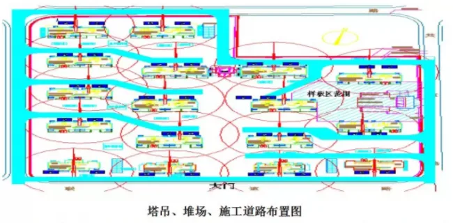
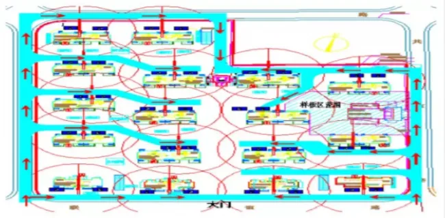
The construction site will be prepared with essential infrastructure including road, water, and electricity connections, as well as leveling. Temporary facilities and PC structure storage yards will be established. To meet lifting requirements for heavy PC components, each building will have a QTZ100 tower crane strategically positioned to enable an average node lifting every 5 to 6 days. Due to simultaneous construction of seven buildings, tower cranes are densely arranged with overlapping radii. An anti-collision plan for tower cranes has been developed, ensuring safe and efficient operation.
Due to the large volume and multiple sections of PC components, as well as the high-rise nature of the buildings, unloading and stacking are challenging. Using truck cranes during unloading greatly enhances construction progress and reduces tower crane load, improving overall efficiency. This approach is recommended based on prior experience.
(2) Off-Site Preparation
Continuous communication with PC manufacturers is maintained to coordinate production schedules and delivery times. On-site investigations determine manufacturers’ capacities and the types of PC components produced. Manufacturers are invited to visit the site to review transportation routes and road conditions. Quality inspections are conducted at manufacturing sites, with non-conforming PC components rejected or corrected before delivery.
2.2 Engineering Objectives
2.2.1 Safety Construction Objectives
Achieve zero major injuries, no public safety incidents, criminal cases, or fires.
2.2.2 Civilized Construction Objectives
Maintain a civilized construction environment recognized within Baoshan District, Shanghai.
2.2.3 Quality Objectives
Achieve a 100% first-pass acceptance rate. Operators will be thoroughly trained on key points before lifting operations to ensure quality standards are met on the first attempt.
2.2.4 Progress Construction Objectives
Complete all construction milestones on schedule by allocating adequate labor, machinery, and management resources, and managing these effectively to maintain orderly progress.
Part 3: Factory Production and On-site Construction of PC Structures
3.1 PC Structure Factory Production
3.1.1 Component Selection and Production Scope
All PC prefabricated components will be produced in factory settings by specialized manufacturers. Finished components are transported to the site for unloading, lifting, and installation by the general contractor. Components include prefabricated exterior wall panels, stairs, balconies, protruding window panels, and equipment platforms.
3.1.2 Equipment and Facilities
- Concrete mixing: forced mixer
- Molds: steel forming molds
- Concrete transportation: 6m³ mixer trucks
- Concrete vibration: high-frequency insertion vibrators
- Steam curing: 4-ton boiler with pipelines
- Crane: truck crane with over 12-ton capacity
3.1.3 Factory Production and Construction
1. Reinforcement Engineering
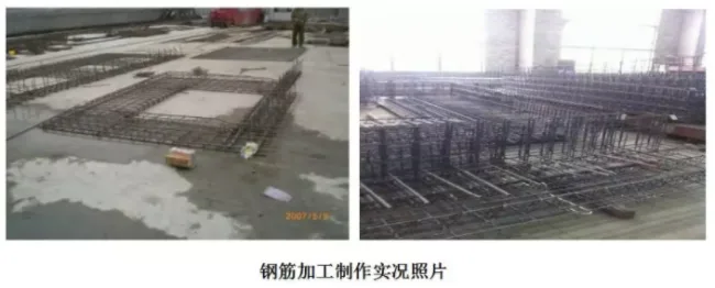
Steel bar cutting, welding, and forming are performed in the steel bar workshop with strict size control, maintaining deviations within 1.5 times the allowable limit. Welding follows JGJ18 standards, including pre-shift and batch tests. Due to thin protective layers in panel components, precise reinforcement skeletons and specialized forming frames are essential.
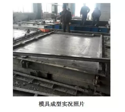
2. Mold Design and Production
The interior surfaces of laminated boards and stairs require high precision and smooth finishes. Molds must offer rigidity, strength, and stability with extremely flat surfaces. Walls and slabs use flat formwork consisting of bottom, outer, and inner forms to ensure smooth exposed surfaces. Molds are cleaned thoroughly, with isolation agents applied carefully to prevent defects. Proper installation and fixation of molds are crucial.
3. Window Frame Installation
Limit frames matching window frame inner diameters are installed on molds, allowing direct window frame fixation with flexible rubber cushions to prevent damage. Upper and lower window frames use detachable templates fixed to the limit frame and main mold. Contact surfaces are sealed with double-sided adhesive tape. Embedded parts and connectors are stainless steel or rust-treated metal, precisely positioned and spaced according to drawings. Doors and windows are installed to ensure horizontal and vertical alignment.
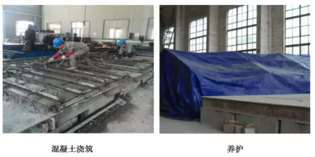
4. Concrete Pouring, Compaction, and Curing
Prior to pouring, formwork, brackets, steel reinforcement, and embedded parts are inspected and approved. Concrete is vibrated using insertion vibrators at 30cm intervals until no air bubbles appear, ensuring a flat, consistent surface with cement slurry on top. Continuous monitoring for abnormalities is required; pouring is stopped if issues arise.
Low-temperature steam curing is applied directly on molds using oilcloth covers supported 300mm above the surface to allow steam circulation. Overlapping oilcloth is sealed tightly to form a curing environment with stages including steaming nutrients, heating, constant temperature (55 ± 2 ℃), and cooling, with controlled rates not exceeding 15 ℃/h for heating and 10 ℃/h for cooling.
Steam curing duration is extended at ambient temperatures below 15 ℃. Oilcloth removal occurs only when temperature differences between cured components and ambient air are under 20 ℃.
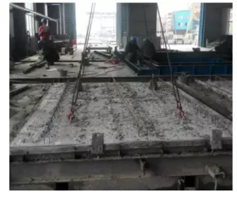
5. Mold Removal
Formwork and movable components are removed only after concrete achieves at least 70% of design strength. Pressure thermometers are used carefully, avoiding bending of capillary tubes beyond a 50mm radius. Walls and slabs, poured horizontally, are lifted and rotated 90 degrees to vertical positions using specialized techniques. After demolding, cast-in-place concrete connection parts are chiseled.
3.2 PC Structure Transportation, Storage Yard, and Finished Product Protection
3.2.1 Transportation
Vertical transportation is prioritized to minimize damage and simplify installation. Before loading, lifting frames are installed, and PC components are secured with soft isolation to prevent damage during transport.
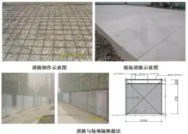
To ensure smooth entry and circulation on site, main entrance roads with a minimum width of 8 meters and onsite roads of 5 meters are established, allowing two-way traffic and easy maneuvering for transport vehicles.
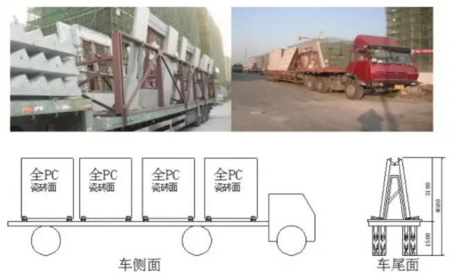
PC balconies, air conditioning panels, stairs, and equipment platforms are transported flat, secured with full-length wooden strips and tight ropes. Stacking limits are strictly observed: no more than six balconies or air conditioning panels stacked, and no more than three balcony and stair panels stacked.
Vehicles should accelerate and decelerate smoothly, reducing speed during turns to prevent overturning.
Transport routes passing over underground garages are reinforced using 16# I-beams to support the static load.
3.2.2 Storage Yard
Due to large single-piece sizes and weights (up to approximately 4.6 tons and 4 meters long), two storage yards per building, each 10m by 20m, are established. Most yards are located on basement roofs with reinforced fire lanes. Surrounding construction roads and yards have reinforced concrete and steel rebar for load support.
Space constraints require the basement roof to serve as both construction roads and material yards during main construction phases, with steel pipe reinforcements applied and removed after structure capping.
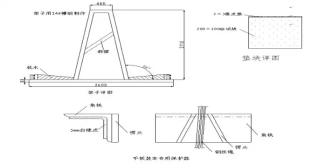
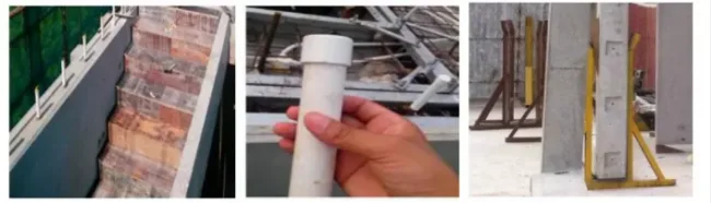
After delivery, PC components are lifted by tower or truck cranes to designated storage areas, stacked on sleepers with anti-overturning measures. Wall panels are stored vertically with channel steel supports at bottom ends on flat, sturdy surfaces. Temporary fixation and site enclosures are implemented to prevent damage from collisions or crane movements. Components are stacked orderly with gaps in between to avoid domino effects.
3.2.3 Finished Product Protection
Protection during transport, stacking, and lifting is critical. Steel frames assist transportation, with cushioning using cotton yarn or rubber blocks at contact points to prevent damage, especially since exterior wall panels are finished with tiles. During stacking, steel poles maintain balance and stability, with padding under components to absorb shocks. Stairs and balconies are stacked individually on wooden blocks that exceed exposed stirrup heights, with cushioning for flexibility.
During lifting and installation, plastic gaskets are placed to reduce damage during fine adjustments. Stairs and balconies are covered with wooden boards for protection. Sleeve connection bars are shielded with PVC pipes during concrete pouring to prevent contamination and ensure smooth subsequent lifting.
3.3 On-Site Construction of PC Structure
3.3.1 Construction Process and Breakdown Diagrams
1. Construction Process
PC construction follows this sequence:
- Axis control measurement
- Floor snap line marking
- Horizontal elevation measurement
- Installation of prefabricated wall panels one by one, including cushion block placement, lifting and positioning, temporary fixation, decoupling and correction, adhesive rubber application, connection plate installation, and anchor bolt sorting
- Reinforcement binding of cast-in-place shear walls with embedded mechanical and electrical pipes
- Shear wall formwork and support frame erection
- Installation of stacked balcony panels and air conditioning panels
- Reinforcement binding of cast-in-place floor slabs with embedded pipes
- Concrete pouring, compaction, and curing
- Installation of prefabricated stairs
- Removal of scaffold frame structures
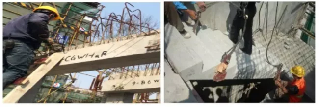
- Grouting construction
- Continuation of lower structure construction following the above process
Grouting construction includes connecting grouting steel bars to cast-in-place steel bars, placing cover plates, steel bar adjustment, casting concrete, and high-strength grouting after main structure completion on each floor.
2. Process Breakdown Diagrams
Diagram 1: Mark floor lines and measure horizontal elevation. Position floors according to PC board numbers. Tower crane operates clockwise as shown:
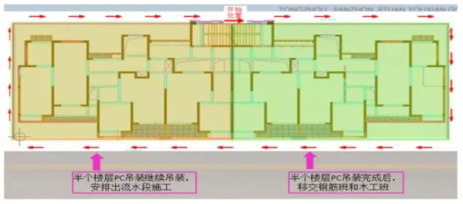
Diagram 2: Exterior wall panels lifted and installed per PC structure lifting sequence.
Diagram 3: Binding of shear walls and column steel bars.
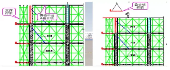
Diagram 4: After lifting and calibrating exterior wall panels, shear walls, beam support formwork, floor formwork, and stacked balcony panel racks are constructed separately following Japanese formwork techniques.
3.3.2 Construction of Lifting Facilities
1. Lifting
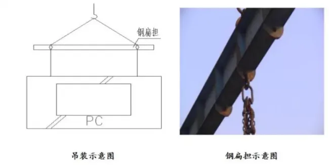
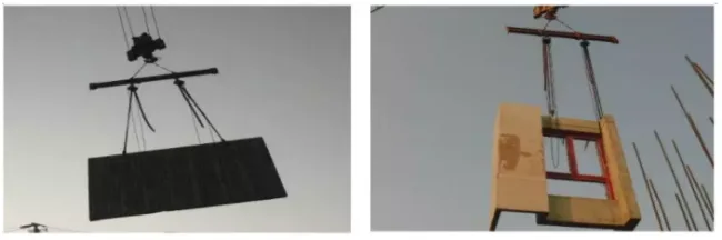
The maximum weight of single components is approximately 5 tons, lifted using a TC6517B tower crane. To avoid deformation from single-point lifting, steel poles are used to achieve horizontal lifting. Lifting points are strategically placed to prevent damage to component edges and corners. Components are moved at constant speeds and manually aligned during placement.
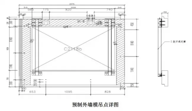
2. Pre-embedded Lifting Points
Lifting points for prefabricated exterior wall panels are classified into two types: pre-embedded hooks within the formwork, and embedded bolt sleeves along the PC structure. High-strength bolts with lifting rings are screwed into bolt sleeves, and steel poles are used to lift components into place.
3. Component Reinforcement
Large, thin components such as PCF boards and protruding window panels are prone to deformation or fracture during lifting and require reinforcement.
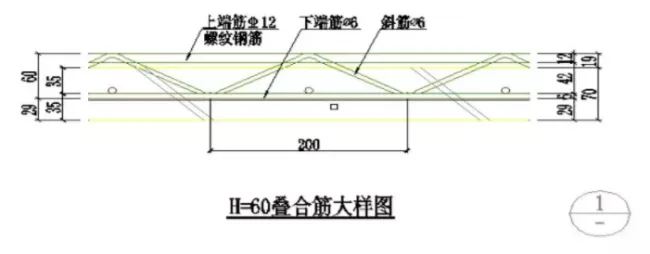
(1) Composite Reinforcement:
Triangular composite reinforcements are welded to main internal reinforcement bars on PC boards and balcony panels to form integrated units.
(2) Steel Reinforcement:
For complex components or those unsuitable for composite bars, steel section reinforcements are added. The factory provides 1-2 sets of these reinforcements for lifting and flipping operations.
3.3.3 PC Structure Installation and Adjustment
1. Exterior Wall Panel Construction
(1) Conditions for Assembly Components:
- Quality inspection, numbering, and quantity verification upon arrival.
- Cleaning placement points, adjusting screws per elevation control lines, and applying water stop strips.
- Positioning wall panels and floor limit devices by axis and control lines, reinforcing inner sides to strengthen inter-panel connections.
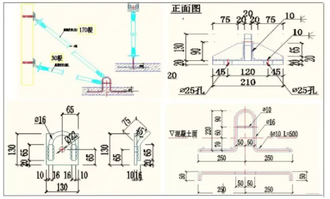
- Setting up component supports and temporary fixation. Plate-to-plate connectors are installed per drawings. Vertical size adjustments use diagonal braces and steel shims (1mm, 3mm, 5mm, 10mm, 20mm) on site rather than bolts.
- Decoupling tower crane lifting points before installing the next panel, repeating this cycle.
- After concrete pouring and compaction meet strength requirements, supports and temporary fixations are removed.
(2) Wall Panel Construction Method:
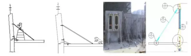
- The temporary support system uses adjustable long and short diagonal screws.
- Using horizontal elevation and axis control, supporting parts are installed under panels. Hard cushion blocks matching wall thickness are placed at panel bottoms, with soft mortar spread beneath. The panel is lifted and placed in one step.
- Verticality is checked with rulers and plumb bobs; deviations are corrected using adjustable diagonal rods.
- Multi-specification steel gaskets (sizes 40×40 mm, thicknesses 1mm to 20mm) regulate elevation, designed for Grade II steel load capacity.
- After installation and fixation, construction proceeds following the structural layer process.
2. Prefabricated Balcony Panels
- Panels are delivered, numbered, and quantity verified per lifting schedule.
- Temporary fixing and shelving scaffolds are installed.
- Elevation control and panel body lines are established.
3. Prefabricated Staircases
- Access, numbering, and quantity counting by unit and floor.
- Stairs are hoisted after completion of exterior wall panels and floor formwork scaffolding. The first PC staircase is installed, followed by floor formwork completion and second staircase hoisting. Upper staircases reserve anchor bar positions for later installation.
- Installation sequence: pour shear walls and landings → hoist stairs → anchor and grout.
- Stairs are slowly tilted and lifted from one side of the stairwell, secured at top and bottom with steel bars anchored into cast-in-place floor slabs. Construction gaps are filled with commercial cement mortar after positioning.
- Installation proceeds piece by piece per numbering and lifting sequence.
- Decoupling of tower crane lifting points repeats the cycle.


Must log in before commenting!
Sign Up