The sliding staircase in prefabricated buildings exemplifies the principle of “using flexibility to overcome rigidity.” Its design incorporates sliding supports to provide sufficient deformation space between the staircase and the main structure during earthquakes. This approach helps minimize damage to the staircase caused by seismic activity and ensures safe evacuation routes.
Unlike traditional cast-in-place integral stairs, sliding stairs do not rely on the structural stiffness of the stair itself to resist earthquake forces. This makes them both an economical and advanced design solution. Following the Wenchuan earthquake eight years ago, sliding stairs have become a standard practice encouraged by national regulations and design manuals. Prefabricated stairs are particularly well-suited to realize this design concept.
Prefabricated stairs take full advantage of factory manufacturing, addressing challenges typically faced on-site, such as complex stair formwork support and difficulties controlling concrete pouring and compaction quality.
The on-site installation of prefabricated stairs is rapid, reducing labor intensity and improving efficiency. This is especially beneficial for residential buildings with many identical floors, where stair molds can be reused. Prefabricated stairs represent a component product that best reflects the characteristics of building industrialization.
The standard value for cross-sectional bearing capacity is calculated based on the standard material strength values.
Per Article 7.2.1 of the “Code for Design of Steel Structures” GB50017-2003, the design value of shear bearing capacity for C-grade bolts is specified.
(If the standard shear bearing capacity exceeds the design value, the bolt’s shear bearing capacity is directly taken as the design value of 28kN for safer design.)
If C-grade bolts are not used and HRB400 steel bars are selected, the recommended design shear strength values for the steel bars can be found in Table 3, “Conversion Relationship of Strength Design Values,” on page 176 of Article 3.4.1 in GB50017-2003.
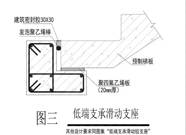
Figure 5.5.5 on page 41 of the national standard atlas “Construction of Prefabricated Concrete Structure Connection Nodes” 15G310-1 illustrates the “Low-End Support Sliding Joint Support” as shown below:
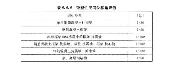
Here, h represents the height of the staircase (with a floor height of 3000 mm, the height for a two-flight staircase is 1500 mm). For the elastic-plastic inter-story drift angle of the structure, please refer to Article 5.5.5, “Table 5.5.5 Elastic Plastic Displacement Angle Limits,” in the “Code for Seismic Design of Buildings” GB50011-2010 (2016 edition), applicable to frame structures.
2. The length of the stair lug should be at least 200 mm to ensure stability and prevent sliding during major earthquakes.
3. The cavity height shown in the figure is greater than 10 times the diameter (10d), allowing the stairs to release displacement during seismic events. If the cavity diameter is set to 50 mm, the permissible deformation for the staircase to slide freely is limited. As noted earlier, if the staircase displacement during a strong earthquake is hindered by the bolts, sliding support cannot be formed effectively. Whether the cavity’s diameter and size are optimal requires further scientific discussion and experimental validation.
4. The sliding hinge support must include an “isolation layer” such as felt at the contact surface. Without this isolation layer, the horizontal friction coefficient between the platform beam lug and cement mortar is generally around 0.4 or higher (refer to “Table 6.7.5.5-2” in Article 6.7.5 of the “Code for Design of Building Foundation” GB50007-2011). This friction prevents sliding deformation, which contradicts the design intent. Engineers must emphasize this requirement in design documents and strictly adhere to node details to avoid on-site errors. Past projects have shown errors where reserved deformation spaces were filled with cement mortar, completely violating construction and design principles.
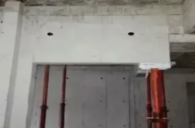
5. High-end support uses a “fixed” hinge support. The reserved holes on the stair board should be filled with grouting material with a strength not less than 40 MPa. Conversely, low-end support uses a “sliding” hinge support that must retain the cavity. See Figure 1 for details. For different stair sections, both high-end and low-end platforms may exist at the same elevation (as shown in Figure 2). For example, stair section DT2 at elevation 5.890 is a low-end platform, while stair section DT1 at the same elevation is a high-end platform. During installation and grouting, there are four holes at this elevation (Figure 1), which on-site workers often confuse and fill all with grout. This prevents the low-end sliding deformation intended by the design, posing a safety risk.
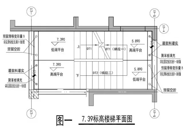
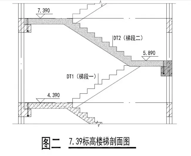
6. To reduce complexity and errors on the construction site, it is recommended to place fixed hinge supports at the same stair elevation (e.g., elevation 7.390 in Figures 1 and 2), and sliding supports at the opposite end (elevation 5.890 in Figures 1 and 2). At the sliding support end, no bolts should be installed, as shown in Figure 3.
Buildings generally have structural and enclosure components around the staircase, preventing it from falling during earthquakes. For important buildings with high pedestrian traffic, the potential impact of staircase movement on surrounding structural elements during major earthquakes should be considered. Structural design can refer to Article 3.6.2 (1) of the “Code for Design of Concrete Structures” GB50010-2010 (2016 edition) and Article 3.12.6 of the “Code for Design of Concrete Structures of Tall Buildings” JGJ3-2010 for collapse prevention strategies.
The three-node sample shown below is simple to fabricate, easy to install on-site, and resistant to displacement, meeting the requirements for sliding bearing designs. To ensure consistency in factory manufacturing and avoid errors in reserved holes, factories can reserve two holes on each side during production. Before installation, the reserved holes at the sliding end can be pre-sealed with mortar.
In conclusion, a successful design concept relies on precise node design and construction. Designers must provide clear drawings, highlight critical points and potential error-prone areas, enabling factory workers and on-site personnel to fully understand the design intent and the sliding stair principle under stress.
Only through close coordination among design, factory manufacturing, and on-site construction—strictly following drawings and controlling crucial details—can good design concepts be effectively realized in actual projects.


Must log in before commenting!
Sign Up