1. Characteristics of Prefabricated Buildings
1.1 A wide range of building components—including exterior wall panels, interior wall panels, composite panels, balconies, air conditioning panels, stairs, prefabricated beams, and columns—are manufactured and processed off-site in workshops.
1.2 On-site assembly operations are extensive, significantly reducing traditional cast-in-place construction tasks.
1.3 Integrated architectural and decorative design and construction allow for simultaneous execution of decoration and main construction work, optimizing project timelines.
1.4 Standardized design combined with digital management enhances production efficiency. The more standardized the components, the higher the efficiency and the lower the component costs, improving overall cost-effectiveness.
1.5 Prefabricated buildings support green building requirements, promoting sustainable construction practices.
2. Lifting Sequence Planning
Determine the quantity and types of tower cranes required based on floor plans. Establish the lifting sequence for components to ensure smooth and alternating progression of construction processes.
3. Technical Workflow and Process Breakdown
3.1 Workflow
Begin with measurement and control axis setup, followed by floor snap lines and horizontal elevation measurements. Install prefabricated wall panels sequentially, including the placement of control elevation cushions, lifting and positioning, temporary fixation, adjustment, and anchor bar installation. Proceed with steel bar binding for cast-in-place shear walls (including pre-embedded mechanical and electrical conduits), formwork setup for shear walls, installation of prefabricated stairs, balconies, and air conditioning panels. Then bind steel bars for cast-in-place floor slabs (with embedded conduits), pour and compact concrete, and cure accordingly. Repeat this process for floors 2 through 11.
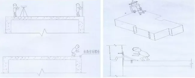
3.2 Process Breakdown Diagram
Step 1: Mark floor lines and measure horizontal elevations.
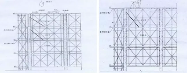
Step 2: Lift exterior wall panels in the designated direction.
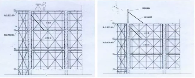
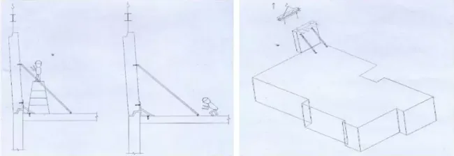
Step 3: Complete external wall panel lifting and calibration.
Step 4: Bind steel bars for shear walls and columns.
Step 5: Post-pour treatment of shear walls, beam formwork setup, floor slab erection, and prefabricated beam rack installation.
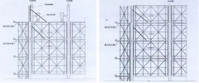
Step 6: Hoist prefabricated beams and composite panel components.
Step 7: Perform subsequent floor construction tasks, such as beam and slab reinforcement.
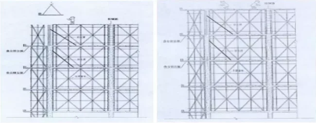
Step 8: Pour, compact, and cure floor concrete.
Step 9: Repeat the above process for the next floor.
4. Prefabricated Interior and Exterior Wall Hoisting Construction
4.1 Lifting Method
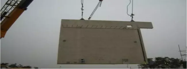
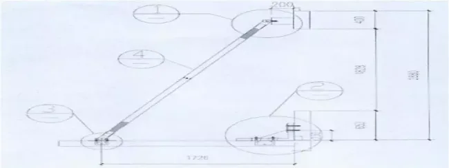
This project utilizes tower cranes for lifting. To prevent component deformation caused by single-point lifting, steel poles are used for lifting and positioning. Lifting points on components are carefully arranged to ensure horizontal lifting and to avoid damage to edges and corners. Once lifted smoothly, the crane arm moves at a constant speed to approach the building, where manual adjustments center the prefabricated component in place.
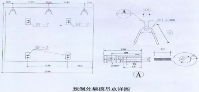
Wall Panel Hoisting Diagram
4.2 Pre-embedded Lifting Points
Prefabricated concrete exterior wall components incorporate hanging points and embedded support elements to facilitate lifting.
4.3 Conditions for Wall Assembly Components
Condition 1: Upon arrival at the site, assembled components are numbered and counted according to the lifting sequence.
Condition 2: Clean the placement areas for each component and position hard cushion blocks according to elevation control lines.
Condition 3: Install limit devices for wall panels and floor slabs based on axis lines and control markings, verifying numbering and lifting order.
Condition 4: Set up component supports and temporary fixations, adjusting vertical dimensions of the wall panels.
Condition 5: Disconnect tower crane lifting points, install the next panel, and repeat the process.
Condition 6: After concrete pouring and curing meet design specifications, remove supports and temporary fixations.
4.4 Prefabricated Wall Panel Construction Method
4.4.1 Temporary support systems for prefabricated wall panels consist of two sets of channel steel limits and two sets of adjustable diagonal screws. For heavier or cantilevered components, additional horizontal connections and adjustable screws are used to ensure safety.
4.4.2 Using established horizontal elevation and control axes, install supports beneath panels according to these control lines. The base of the walls uses hard cushion blocks matching wall thickness, combined with mortar to create a stable placement surface before lifting panels into position.
4.4.3 After placement, check panel verticality with a ruler and adjust with an adjusting rod if necessary.
4.4.4 Panels are fixed to cast-in-place structures via adjustable screws made from 45# medium carbon steel, designed to meet Grade II tensile strength standards.
Subsequent construction proceeds according to structural layer procedures once panels are installed and secured.
5. Prefabricated Beam Hoisting Construction
5.1 Inspection, Acceptance, Numbering, and Marking of Prefabricated Beams
5.1.1 Ensure concrete strength reaches design specifications before lifting beams.
5.1.2 Inspect beams for integrity, checking for distortions, fractures, damage, geometric accuracy, embedded parts, lifting rings, and surface treatment compliance. Organize beams on-site according to lifting sequence and marking numbers.
5.2 Hoisting Process Flow
The installation steps for each prefabricated beam include binding lifting components, lifting, positioning, calibration, securing, disconnecting, and proceeding to the next beam.
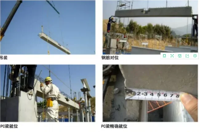
During lifting, ensure secure and stable connections between lifting components and hooks. Maintain slow, steady movement without sudden starts or stops. Crane operators must prioritize safety throughout.
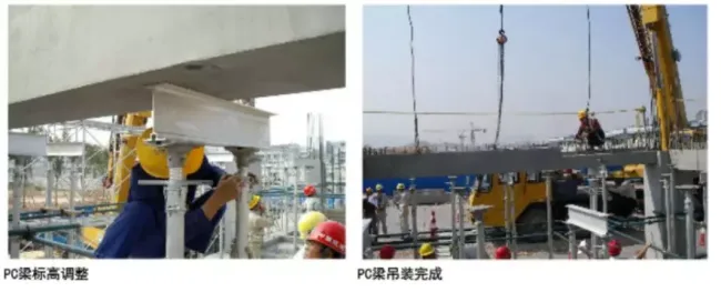
When lowering the beam onto supports, carefully align with reference lines. Adjustable supports allow fine-tuning of beam elevation during placement.
Use steel wires aligned with the beam’s centerline or at regular intervals to straighten beams horizontally and vertically. Adjust supports as needed and secure once aligned.
After final positioning, weld and fix steel reinforcements between beams and columns as specified. Then proceed with lifting the next beam.
Prefabricated Beam Support Diagram
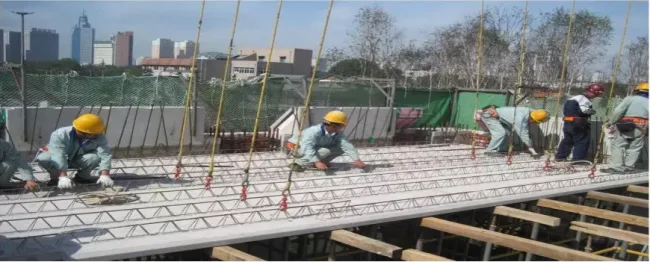
6. Construction of Truss Reinforced Concrete Composite Panels
6.1 Unloading and Stacking
1) Store panels within crane reach on a flat, stable surface suitable for stacking.
2) Before unloading, verify that lifting equipment and pre-embedded lifting rings are securely fastened. Only then proceed with slow lifting.
3) Stack truss reinforced panels and decorative panels separately, limiting stacks to no more than four panels.
4) Ensure stacks have at least four supporting points, preferably using wooden blocks as cushioning to protect panel surfaces.
6.2 Installation Preparation
Position walls at laminated panel locations. Install elevation positioning square steel bars (25mm wide) on wall formworks. Adjust elevation prior to pouring concrete to ensure correct height and flatness.
Inspect and adjust the top surfaces of walls or beams supporting the slabs. Remove any excess height and fill low spots as per grouting standards. Straighten and align reinforcing steel bars to avoid interference with panel placement.
6.3 Setting Up Temporary Support Frames
Provide full temporary support below laminated panels using integrated decorative supports. Adjust support elevation to match the reserved wall elevations on both sides before floor slab installation.
6.4 Installation Process and Requirements
1) Use composite panel lifting equipment to ensure even load distribution and component stability, preventing cracks or twists.
2) Slowly lift panels with a tower crane, pausing when the bottom edge reaches 500mm above ground to inspect for secure hanging and surface integrity. Address any issues before continuing.
3) Install composite panels vertically from top to bottom, pausing 20cm above the working surface for manual alignment. Avoid collisions between reserved steel bars on panels and walls. Lower panels steadily to avoid impact damage. Cease lifting operations if wind exceeds level 5.
4) Use wooden blocks as cushions when adjusting panel positions. Avoid using pry bars directly to prevent edge damage. Ensure panel length placement within 5mm tolerance.
5) After installation, perform standard calibration and adjust the supports beneath the slab accordingly.

Panel Lifting Location Diagram

Installation Process Diagrams
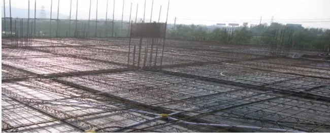
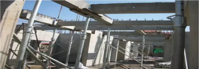
Overall Effect Demonstration
6.5 Construction of Board Joints and Laminated Layers
Laminated steel bars are arranged as double-sided, single-layer reinforcements. Clean debris from composite panels before binding steel bars, which must be accurately spaced and inserted into the truss during binding. The orientation of steel hooks must be controlled to remain upright.
For two-way reinforcement placement, when diameters and spacing are identical, place the shorter span reinforcement below the longer span. If diameters or spacing differ, position the direction with larger reinforcement beneath the smaller.
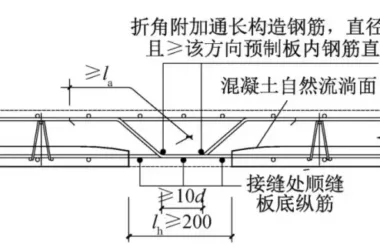
Steel bars at joints must be precisely placed, avoiding omissions or misalignments. Formwork must be installed beneath joints when pouring concrete.
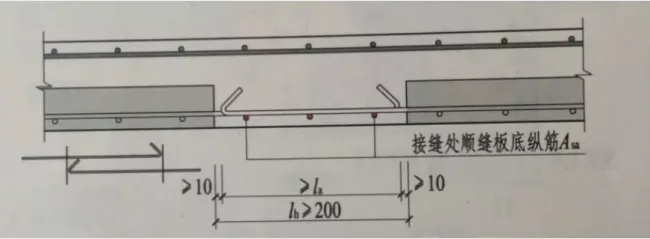
Double-Directional Board Joint Method
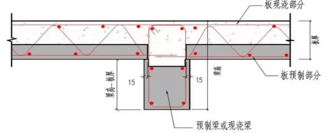
Connection Between Prefabricated Panels and Beams
7. Construction Plan for Prefabricated Stairs
7.1 Node Description
Prefabricated stairs connect to beams with one end fixed and the other sliding. Railing holes are reserved at specific locations on stair sections, allowing stair railings to be anchored with grout anchors.
7.2 Process Flow
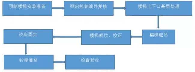
7.3 Installation Preparation
Review drawings thoroughly, verify component numbers, confirm installation positions, and establish the lifting sequence.
7.4 Control Line Setup
Mark staircase installation control lines based on construction drawings. Review both control lines and elevation. Leave a 20mm gap between the staircase side and structural wall for plaster layer installation, and reserve gaps in stairwells for railing installation according to specifications.
7.5 Surface Preparation
Before lifting, clean mortar and debris from embedded stair parts to ensure proper connections. Apply a 20mm thick leveling layer of 1:1 cement mortar (minimum strength M15) on upper and lower ladder beams, controlling elevation accurately.
7.6 Staircase Lifting
Lift prefabricated stair slabs horizontally, connecting universal lifting ears to embedded lifting nuts with bolts. Confirm secure release buckle rings before slowly lifting.
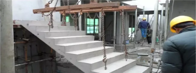
Stair Lifting Diagram
7.7 Stair Panel Positioning
Pause briefly when the stair panel reaches 500mm above the working surface. Carefully adjust the orientation before slow and gentle placement. Avoid rapid or forceful movements to prevent damage from vibrations.
7.8 Staircase Section Alignment
Once the stair panel is roughly in place, fine-tune alignment using pry bars according to control lines. Ensure bolt holes and reserved bolts are centered and properly aligned.
7.9 Staircase Placement
After alignment, level the stair section and grout pre-embedded bolts and reserved holes with specialized materials. Seal holes with mortar.
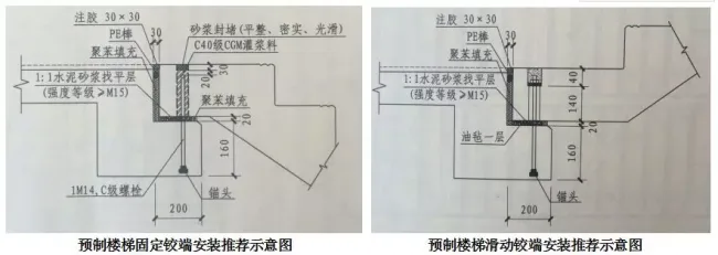
7.10 Gap Treatment (Recommended)
After grouting reserved holes, fill gaps between stair panels and rest platforms with polystyrene. Seal with PE rods and inject adhesive. Follow drawing specifications when applicable.
7.11 Installation and Protection of Prefabricated Stair Panels
7.11.1 Limit stacking of prefabricated stair slabs on-site to no more than four layers, placing wooden pads beneath lifting points.
7.11.2 After installation, protect stair surfaces by nailing multiple layers of boards to form a continuous step shape, securing both sides with additional boards.
Article source: Self-study platform for real estate developers


Must log in before commenting!
Sign Up