1. Project Overview
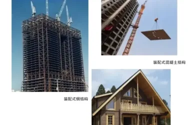
Japan is located in an earthquake-prone region, where small tremors are a common experience for its citizens. Remarkably, even during the massive 9-magnitude earthquake on March 11, 2011, no houses collapsed. So, how was this achieved? Many buildings in Japan use prefabricated construction, assembling columns and beams on-site. But are these prefabricated houses truly safe during major earthquakes? Let’s explore how Japan’s prefabricated super high-rise buildings achieve their impressive earthquake resistance.
Using a fully prefabricated super high-rise structure in Honhachiman, Tokyo as an example:
1. Basic Structure
This building features a frame structure with a height of 144.2 meters. It has 42 floors above ground, each with a standard floor height of 3.3 meters, and one basement level supported by a pile foundation.
2. Layout and Shape
1. The building’s shape is symmetrical, with an outer frame length of 41.4 meters and an aspect ratio of 3.48. The regular floor plan and compact shape are fundamental for enhancing earthquake resistance.
2. Both the inner cylinder and outer ring are composed of prefabricated concrete (PC) frames, including PC columns and beams. Inside the inner cylinder, a steel frame (as shown in the diagram) is constructed using steel columns and beams, serving solely as a mechanical lift parking garage—not as part of the lateral force-resisting system.
Frame structures are the standard choice for high-rise buildings in Japan. Shear walls are typically reserved for low-rise and mid-rise buildings because their seismic performance is less predictable compared to frames. More importantly, frame structures are more flexible, allowing them to endure larger deformations. According to Japanese standards, the inter-story drift angle (the horizontal displacement of a floor divided by its height) for frame structures can be as large as 1/120, whereas in China it is limited to 1/550. Japan prefers allowing buildings to “sway appropriately to dissipate energy” during earthquakes rather than “rigidly bearing” the forces. Combined with seismic isolation and damping technologies, Japanese frame structures can reach heights of up to 200 meters.
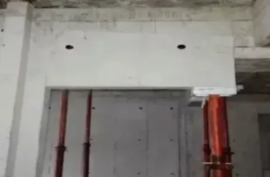
3. Use of Shock-Absorbing Columns
The principle behind shock absorption is that when an earthquake strikes, flexible buildings begin to sway, and all the energy generated must be absorbed by shock-absorbing columns to protect the main structural columns and beams from damage.
These shock absorbers are placed on two spans on each side of the three-span PC column in the inner cylinder—two on each side, totaling eight per floor. From the 1st to the 29th floor, 232 shock-absorbing columns are installed.
▲ The two spans on each side of the inner cylinder’s three-span PC column
▲ Layout from the 1st floor to the 29th floor
Because of its high stiffness, the inner tube frame carries a significant horizontal load—approximately 60% to 80% of seismic and wind forces. The deformation is especially pronounced at the corners of the inner cylinder, so placing shock absorber columns there maximizes their energy-absorbing function and protects the main structure. Shock absorbers are installed up to three-quarters of the building’s height because the bottom supports the primary horizontal shear force and overturning moment. Although displacement increases towards the top, the drift angle remains within safe limits. Additionally, the presence of absorbers in the lower three-quarters effectively controls acceleration at the top.
The shock absorber column consists of two symmetrical steel plates with flanges at the top and bottom, securely connected to the beams, and a relatively soft steel section (with a low yield point) in the middle.
In high-rise bending-shear structures, the maximum horizontal shear force usually occurs mid-floor. Using lower yield point steel here fully utilizes its capacity to absorb shear forces and dissipate deformation energy. The thickness and size of the soft steel section are carefully calculated to ensure durability under large, cyclic shear deformations during major earthquakes.
Prefabrication Research and Development
Construction drawings show variations in shock absorber column models between the 1st and 6th floors. From the 7th to 29th floors, a unified model is used, differing only in the soft steel plate thickness and connection details between the upper and lower steel plates.
▲ Layout of Shock Absorber Columns on Floors 7-29
The net height of each shock absorber column is 2800 mm, divided into three sections. The upper and lower sections (highlighted in red) are reinforced with stiffeners, while the middle section is composed of soft steel.
Stiffeners are installed at both ends and fixed between the upper and lower beams using anchor rods. The beams are PC beams with pre-drilled anchor holes. The stiffeners’ anchor rods pass through these holes and are fastened securely with anchor plate screws.
▲ Connection between anchor rod and beam
▲ Connection between shock absorber column and beam
This technology is not only fully implemented but also prominently featured in building brochures. The shock-absorbing columns are emphasized as a key seismic safety feature, with clear visuals that help customers understand their importance.
4. Additional Earthquake Safety Measures
– **Deformation space between door frames and doors:** Even if the door frame deforms during an earthquake, the design ensures that doors can still open, allowing occupants to escape safely.
▲ Diagram illustrating door frame gap deformation
– **Elevator earthquake induction control:** When a longitudinal seismic wave is detected, the elevator’s earthquake induction system activates immediately, stopping the car at the nearest floor and opening the doors to prevent operation during shaking.
▲ Elevator earthquake induction control system
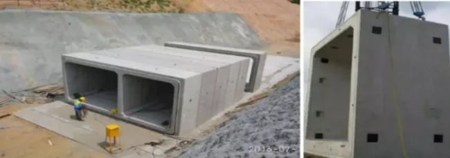
The Key to Full Prefabrication: Strong Connections
Besides adopting advanced seismic mitigation technologies, the strength and quality of prefabricated structural connections (nodes) are critical. Only with robust node connections can the seismic performance of prefabricated buildings match or exceed that of cast-in-place structures.
2015-07-18 10:47:51 Source: China Testing Network | Read: 1290 times
▲ Beam sleeve connection
▲ Prefabricated column head steel reinforcement bars
Vanke’s Applications
Beijing Vanke’s Jinyu Tixiang project is China’s first industrial seismic isolation project. It features 18-story prefabricated shear walls combined with seismic isolation bearings. In Beijing, where the seismic fortification level is 8 degrees, these slightly rigid prefabricated shear walls are separated from the foundation by a seismic isolation layer, effectively reducing seismic impact by 70%.
▲ Construction of isolation layer
▲ Seismic isolation bearings


Must log in before commenting!
Sign Up