Source: Building Industrialization Innovation Alliance
Chapter 3: Lifting Operations of Prefabricated Concrete Components
Content Summary
The lifting operation of prefabricated concrete components is a crucial process that involves lifting, positioning, and adjusting these components throughout the construction of prefabricated buildings. This process completes the temporary positioning of the components on site. This chapter provides a comprehensive overview of lifting operations, covering the types and characteristics of commonly used lifting machinery, selection criteria for lifting equipment, and specific lifting procedures for various prefabricated concrete elements such as wall panels, floor slabs, beams, stairs, and others.
The chapter begins by detailing the selection and matching of equipment and tools during the initial stages of lifting operations, establishing relevant guidelines. It then offers an in-depth explanation of the lifting process, methods of operation, temporary fixing facilities, and critical considerations for different types of prefabricated concrete components.
3.2 Types and Selection of Lifting Equipment
2. Tower Crane Selection and Installation
1) Selection and Positioning of Tower Cranes
Typically, the selection of tower cranes depends on factors such as the building’s structural form, the maximum installation height of prefabricated components, their weight, and the volume of lifting tasks. The placement of tower cranes is primarily influenced by the building’s plan shape, component weights, crane performance, and site terrain.
Before selecting a crane, calculate the weight of prefabricated components for each building section to verify that the tower crane’s lifting capacity matches the demands at various reaches, including suitable safety margins. Additionally, consider the crane’s actual lifting torque and the height required for installing components comprehensively.
The selection criteria for tower cranes in prefabricated concrete structures have evolved significantly due to changes in component lifting processes and frequencies. Tower crane positioning is closely linked to construction flow segmentation and workflow direction. Beyond standard selection and installation rules, the following factors should be considered:
- Heaviest Component Consideration: Choose a tower crane model capable of handling the heaviest prefabricated component and the maximum required lifting radius.
- Installation Location: Determine the crane’s installation position based on site conditions, including the building plan, structural type, basement structure, transportation routes for components, and construction flow. The crane should cover the entire site, ideally positioned close to areas requiring heavy lifts. When multiple cranes operate simultaneously, limit their arm lengths and coordinate their working areas to balance lifting workloads.
- Transportation Route Planning: Since many prefabricated components are transported on flat surfaces, plan internal site routes carefully to control slope and turning radius. After selecting cranes, design road layouts considering component weight and installation positions, as well as crane coverage, to optimize component yard locations.
- Load Verification: Cross-check the maximum weight and lifting positions of components with the crane’s lifting performance, including appropriate safety margins to handle unforeseen conditions.
2) Requirements for Tower Crane Attachments
In traditional cast-in-place concrete structures, crane anchoring points are set on beams, columns, or shear walls. These points can be reinforced locally to meet stress requirements, allowing sufficient time for concrete to cure. However, prefabricated concrete structures progress rapidly, and the structure may not be fully formed when anchoring is needed. Additionally, prefabricated exterior wall components may not provide adequate adhesion or structural strength for anchorage, making traditional wet construction methods unsuitable.
To ensure accurate positioning and proper load distribution at anchoring points, maintain the angle of attachment support rods, and shorten attachment periods, specialized attachment tools such as steel attachment beams are required, as shown below.
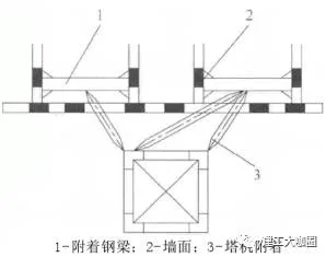
Figure 3-3: Tower Crane Attachment Schematic
3.2.2 Selection of Rigging Equipment
Prefabricated components vary widely in type, weight, shape, and center of gravity. Therefore, lifting points must be pre-designed, and appropriate lifting equipment selected based on these points. Regardless of how many lifting points are used, the vertical line from the crane hook to the lifting device must always pass through the component’s center of gravity to ensure safety.
To ensure stable lifting and prevent swaying, tilting, rotation, or overturning during construction, suitable lifting equipment should be carefully chosen based on calculations.
1. Selection, Connection, and Disposal of Steel Wire Rope
Steel wire ropes are composed of twisted steel wires arranged in strands around a core, often lubricated to reduce friction. They offer high strength, light weight, stability, and resistance to sudden failure, making them reliable for hoisting prefabricated components. Proper selection and safety checks of steel wire ropes are critical to construction safety.
2) Connection Methods for Steel Wire Ropes
There are two main connection methods:
- Small Connection Method: Combines the strands of two ropes within the joint area, resulting in a thicker rope end and shorter joint length.
- Large Connection Method: Involves cutting half the strands from each rope end and interconnecting them, producing a longer joint.
Insertion methods for steel wire ropes include one-in-one, one-in-two, one-in-three, one-in-four, and one-in-five insertions. The most common is the one-in-three method, while the one-in-five is typically used for summarizing ropes.
Fixed connections at rope ends fall into five types: braiding, rope clamp fixing, sleeve pressing, wedge fixing, and lead filling, as illustrated below.
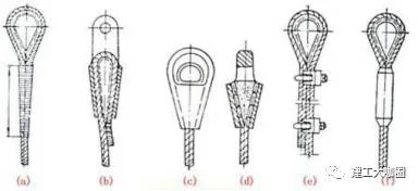
Figure 3-4: Fixed Connection Methods for Wire Rope Ends
Details of Fixed Connection Methods:
(1) Braiding Method
Hand weaving involves manually interlacing six strands of steel wire rope with twisted fiber or metal cores to create sling loops without pre-formed eyes. This method is suitable for loopless buckles, as shown below.
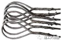
Figure 3-5: Steel Wire Rope Prepared by Braiding Method
(2) Rope Clamp Fixation Method
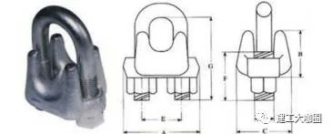
Figure 3-6: Steel Wire Rope Clamp
The rope clamp method is widely used due to its simplicity and reliability. When fixing with clamps, pay attention to the number, spacing, orientation, and strength of the clamps. Recommended quantities are shown in the table below:
| Rope Clamp Specification (Steel Wire Rope Diameter dt in mm) | Minimum Quantity per Set |
|---|---|
| ≤18 | 3 |
| >18 to 26 | 4 |
| >26 to 36 | 5 |
| >36 to 44 | 6 |
| >44 to 60 | 7 |
The distance between clamps should be 6 to 7 times the rope diameter. Correct installation requires securing the clamp saddle on the live section of the wire rope and the U-bolt on the tail end. Clamps must not be alternated along the rope.
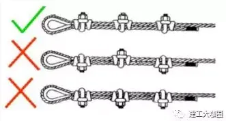
Figure 3-7: Correct and Incorrect Wire Rope Clamp Arrangements
(3) Aluminum Alloy Sleeve Compression Method
Aluminum sleeves are selected according to the steel wire rope specifications and are crimped using either force-limiting or position-limiting methods. The image below shows a wire rope end pressed with an aluminum alloy sleeve.
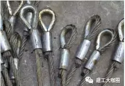
Figure 3-8: Steel Wire Rope End Pressed with Aluminum Alloy Sleeve
(4) Wedge Block and Wedge Sleeve Connection
This method involves wrapping the rope end around a grooved wedge, inserting it into a conical sleeve, and tightening it to secure the rope inside. It is simple, firm, and reliable. Wedge cones are typically made from grade 25 cast steel, and wedges from cast iron or ordinary steel plates. This method is generally used for steel wire ropes under 40mm diameter.
Safety requirements for different rope end fixing methods are summarized below:
| Connection Method | Safety Requirements |
|---|---|
| Braiding Method | Minimum braiding length of 15 times the rope diameter or 300mm; connection strength ≥ 75% of rope breaking force. |
| Rope Clamp Fixation | Number and arrangement per GBT5976-2006; connection strength ≥ 85% of rope breaking force. |
| Aluminum Sleeve Compression | Reliable process ensuring tight bonding; strength equals breaking force of rope. |
| Wedge Block Sleeve Connection | Steel wedge sleeves; connection strength ≥ 75% of rope breaking force. |
2. Use and Disposal Standards for Shackles
Shackles are devices used to connect lifting points to steel wire ropes, as shown below.
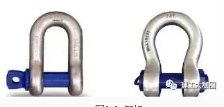
Figure 3-9: Shackle
1) Precautions for Using Detachable Shackles:
- The shackle must bear the load along its centerline axis to avoid bending, unstable loading, or overloading (see Figure 3-10).
- The pin shaft should rotate smoothly without jamming.
- The shackle body should not be subjected to lateral bending moments; load bearing must be within the plane of the body.
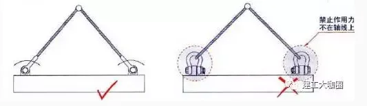
Figure 3-10: Correct and Incorrect Shackle Usage
2) Scrap Standards for Shackles:
- Presence of surface cracks;
- Body distortion exceeding 10%;
- Surface wear exceeding 10%;
- Inability to lock the horizontal pin;
- Horizontal pin deformation exceeding 5% of original size;
- Corrosion or tooth slipping on bolts, as shown below.
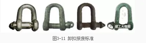
Figure 3-11: Shackle Scrap Criteria
3. Selection of Hoists
Hoists are categorized into manual and power types.
Manual hoists include hand-pulled and hand-operated hoists. These are lightweight, compact, portable, easy to operate, and adaptable to various work environments.
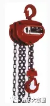
Figure 3-12: Hand-Pulled Hoist
Hand-pulled hoists operate by pulling a hand chain and turning a hand wheel, which actuates friction plates, ratchets, and brake seats. They use multi-speed gears to drive the lifting chain wheel smoothly. Hand-cranked hoists use a lever mechanism to generate linear traction by manually pulling a handle, typically for horizontal movement, whereas hand-pulled hoists are often for vertical lifting.
Power hoists are available with steel wire rope or ring chain suspension. Both electric and pneumatic hoists fall into this category and can be installed on monorail cranes, jib cranes, manual or electric single-beam cranes, gantry cranes, and suspension cranes for material handling. They feature simple structure, ease of manufacture and maintenance, good interchangeability, and user-friendly operation.
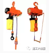
Figure 3-13: Pneumatic Hoist
4. Tool-Type Horizontal Suspension Beam
The lifting tool beam is a versatile, safe, and reliable tool designed for lifting prefabricated components. It is typically constructed by welding I-beams or similar profiles of appropriate size and length.
During operation, steel wire ropes are connected to reserved lifting rings on the prefabricated components via shackles, considering the size, weight, and lifting ring positions. Multiple circular holes are provided along the beam, allowing flexibility to lift different types of components safely and efficiently.
This design replaces traditional single-purpose lifting attachments, enabling the lifting of multiple components with one device and facilitating more organized construction sites.

Figure 3-14: Single-Line Suspension Beam
The adjustable suspension beam features two hooks with adjustable spacing, suitable for lifting prefabricated components of varying sizes while reducing costs. Because the hooks pass perpendicularly through the steel wire ropes and are equidistant from the center, the load remains balanced, preventing tilting and accidents.

Figure 3-15: Adjustable Horizontal Beam with Suspension Points
The “mouth”-shaped suspension beam is especially suitable for lifting L-shaped prefabricated wall panels, enhancing lifting stability.
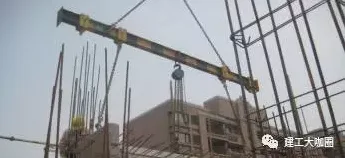
Figure 3-16: Mouth-Shaped Suspension Beam
Note: All materials above are copyrighted by Shanghai Jianfeng College and Shanghai Construction Second Construction Group.


Must log in before commenting!
Sign Up