Source: Building Industrialization Innovation Alliance
Chapter 3: Lifting Operations of Prefabricated Concrete Components
Content Summary
The lifting operation of prefabricated concrete components is crucial for lifting, positioning, and adjusting these elements throughout the construction of prefabricated buildings. It completes the temporary positioning process of the components. This chapter offers a detailed overview of lifting operations, including commonly used lifting machinery types and characteristics, equipment selection, and specific procedures for lifting various components such as wall panels, floor slabs, beams, and stairs.
Initially, the chapter addresses equipment and tool selection and matching for precast concrete component lifting, followed by regulations. It then thoroughly explains the lifting procedures, methods, temporary fixation facilities, and key considerations for different types of prefabricated concrete components.
3.3 Lifting Operation of Precast Concrete Wall Panels
3.3.1 Methods and Reinforcement Measures for Lifting and Binding Prefabricated Components
1) Methods for hoisting and binding prefabricated components
Prefabricated components are bound using two methods: symmetrical binding and asymmetrical non-binding, as illustrated in Figure 3-17.


Figure 3-17: (a) Symmetrical Component Hoisting and Binding (b) Asymmetrical Component Hoisting and Binding
2) Reinforcement Measures During Transportation, Flipping, and Hoisting
For prefabricated components exhibiting lateral stiffness differences, temporary braces can be added for reinforcement. These braces connect to the components via embedded nuts. During transportation, flipping, and lifting, support points are set on these reinforced rods to prevent deformation.


Figure 3-18: Strengthening Measures for Prefabricated Components
3) On-site Flipping Operation Requirements for Prefabricated Components
Flipping is necessary to transport prefabricated components to construction sites for stacking. Typically, four slings are used—two long, two short, and two manual hoists. Before lifting, adjust all slings to equal lengths and tighten them.
The prefabricated component is lifted off the ground, then raised while loosening the manual hoist until it is vertical. Next, loosen the hoist sling beneath the component and place it onto the steel frame.

Figure 3-19: Process of Flipping Prefabricated Components
3.3.2 Placement and Temporary Fixation of Prefabricated Components
Following the installation sequence, lifting personnel must verify the model, specifications, and surface quality of the components before lifting. Once lifted, the installation surface should be leveled horizontally using a chain hoist, and cable wind ropes should be tied at the component’s root.
Mark the positioning axis at the installation site and install temporary supports. Hoist the component into place, align it with the axis, and bolt it to the temporary supports.
Temporary adjustable slant supports should be installed at the upper end. Due to the large exposed surface area of the components, a slow positioning mechanism is recommended to gradually lower the component. Cable wind ropes tied at the root help control rotation and ensure smooth positioning.
To minimize shaking during tower crane hoisting, temporary guide devices can be installed on both the component and installation surfaces for precise, one-time placement. After temporary fixation, the lifting commander must confirm secure connections before loosening the hooks.
3.3.3 Operation Requirements for Lifting Personnel
- Before lifting, inspect mechanical rigging, fixtures, and lifting rings, and conduct trial lifts.
- Maintain unified command and signaling throughout the lifting process.
- When using tools like pry bars, apply force evenly and slowly, ensuring a stable fulcrum to prevent accidents.
- Do not loosen ropes or unhook suspended components before calibration, welding, or fixation.
- Avoid suspending or pausing components mid-lift for extended periods.
- Steel wire ropes must not contact electrical lines, welding grounding wires, or abrasive surfaces.
3.3.4 Hoisting Process for Precast Concrete Wall Panels
(1) Connecting Lifting Machinery
The number and positions of lifting points depend on the panel’s length and cross-sectional shape. Steel wire ropes attach to clamp rings at lifting points. The lifting machinery’s hook connects to the clamp ring within the hook area, ensuring the lifting rope is directly above the lifting point.
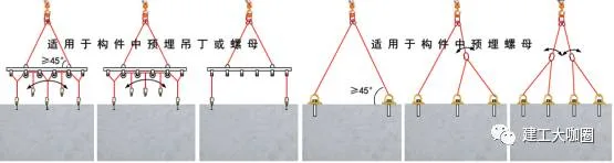
Figure 3-20: Connection Method of Hanging Points for Precast Concrete Wall Panels
(2) Safety Checks and Lifting
Verify the stability of the hook and suspension ring connection and that the suspension chain is evenly loaded. Lift slowly, pausing once the lifting rope tightens to check the automatic snap ring’s reliability and prevent self-detachment.
To prevent swinging during placement, hang a slip rope at the bottom of the panel. Operators should maintain a safe distance and inspect all connections before lifting.
(3) Mid-Lift Procedures
When the wall panel reaches 500mm above the ground, pause briefly to remove protective pads and support legs. Under the signalman’s command, lift the panel to floor level for positioning. Note that tower crane lifting and arm rotation must not occur simultaneously to ensure safety.
(4) Positioning and Temporary Support
Slowly lower the panel to the top of the installation site. Verify the panel number, adjust orientation, and have two workers control placement to ensure precise positioning in all directions. Once seated, add temporary supports for safety. The suspension buckle should only be removed after temporary support installation.
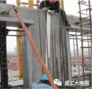
(5) Final Fixation
After vertical alignment, fix the upper and lower support rods and weld them securely to the embedded floor anchors. Seal board seams with adhesive tape strips.
The lifting process of prefabricated concrete wall panels is shown in Figure 3-21.
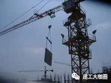
(a) Vertical hoisting of precast concrete wall panels
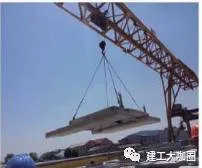
(b) Horizontal hoisting of precast concrete wall panels
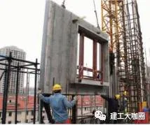
(c) Preparation for installation
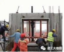
(d) Installation in place
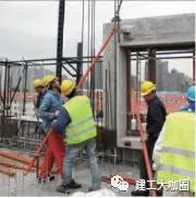
(e) Adding temporary support
(f) Sealing board seams after installation
Figure 3-21: Lifting Process of Prefabricated Concrete Wall Panels
3.4 Hoisting Operation of Prefabricated Concrete Floor Slabs
3.4.1 Prefabricated Composite Floor Lifting Process
(1) Installation of Suspension Points
Each composite floor slab requires four lifting points located at the junctions of the upper chord and web reinforcement of the lattice beam. These points should be positioned between 1/4 and 1/5 of the slab’s length from its ends to ensure even load distribution. The slab must be horizontally adjusted and placed on supports.
Suspension points are created by embedding steel reinforcement rings, as shown in Figure 3-22.
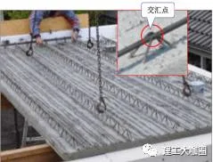
(a) Position at the intersection of the upper chord and web member of the truss reinforcement
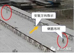
(b) Pre-embedded steel lifting ring
Figure 3-22: Suspension Point Setup for Prefabricated Composite Floor Slabs
Table 3-9: Lifting Point Setting Data
| Width (mm) | Length (mm) | Distance from Edge (mm) |
|---|---|---|
| 1200–2400 | 3000/3300 | 600 |
| 3600 | 700 | |
| 3900 | 800 | |
| 4200 | 900 | |
| 4500 | 1000 |
Due to the relatively thin and large size of the prefabricated composite floor slabs, professional lifting equipment is necessary to prevent uneven stress and structural damage. If any side exceeds 2.5 meters in length, six lifting points should be used. For slabs spanning over 6 meters, use eight suspension points to balance the load effectively, as shown in Figure 3-23.
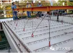
Figure 3-23: Specialized Lifting Equipment
(2) Support Frame Setup Before Hoisting
A support frame, similar to those used for prefabricated beams, must be installed beneath the floor slab before hoisting. The first support should be set 0.2 to 0.5 meters from the slab edge.
The composite floor support system must be vertical, with triangular brackets securely clamped. Support spacing should not exceed 1.8 meters. For spans of 4 meters or more, the middle section should be slightly arched.
The I-beams in the support system must be perpendicular to the lattice beams of the composite floor.
Support Frame Types:
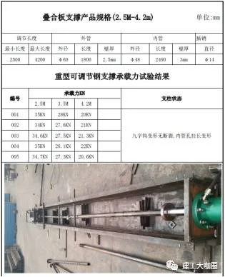
- Independent Steel Columns: These consist of an outer pipe, inner pipe with adjustment holes every 100 mm, fine-tuned threaded pipes, and nuts. They provide vertical support for horizontal prefabricated structures, bearing both self-weight and construction loads. Height adjustments are made using a hook inserted into the inner pipe holes and a fine adjustment nut on the outer pipe, allowing a 130 mm fine-tuning range. These columns can be customized by height and load capacity.
- Folding Tripods: These feature welded legs with a central eccentric lock to secure the steel pillar. Once opened, the tripod’s support rod can be tightened with a hammer strike on the lock, ensuring stability. For transport, the tripod legs retract, allowing easy manual carrying and storage in a box.
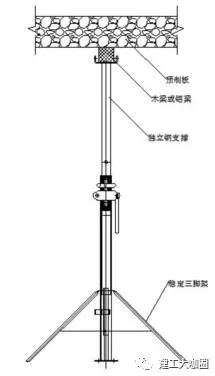
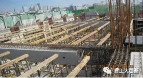
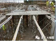
Figure 3-24 & 3-25: Independent Steel Pipe Support and Folding Tripod Support Systems
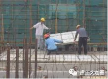
Figure 3-26: Hoisting Process of Prefabricated Composite Floor Slabs
Note: The copyright of the above materials belongs to Shanghai Jianfeng College and Shanghai Construction Second Construction Group.


Must log in before commenting!
Sign Up