Source: Building Industrialization Innovation Alliance
Chapter 2: Transportation and Site Inspection of Prefabricated Concrete Components (Part 2)
Content Summary
Transporting prefabricated concrete components involves moving them from the manufacturing facility to the construction site. Ensuring the quality and safety of these components during transportation is essential. The selection of transportation routes and equipment must meet specific requirements, and protective measures should be implemented to safeguard the components.
Upon arrival, prefabricated components must be accompanied by a concealed acceptance form and a product qualification certificate. Both the construction and supervision teams are responsible for conducting quality inspections. On-site stacking should occur in a dedicated yard, where components are promptly lifted to designated areas using tower cranes. Stacks should be organized by type, size, and lifting sequence, with appropriate protection measures in place.
2.2 Inspection of Precast Concrete Components Upon Arrival
Every prefabricated concrete component delivered to the site must include a concealed acceptance form and a product qualification certificate. The construction and supervision units must perform quality inspections, which cover:
- Verification of quality certification documents and factory identification
- Assessment of the component’s appearance quality
- Measurement of dimensional deviations
Special attention should be paid to matching the component’s drawing number with the actual component, as well as verifying the production date, model, production unit, and acceptance marks clearly displayed on the components.
1) Appearance Quality Inspection
The appearance quality of prefabricated components should be classified based on defect type and severity, following the standards outlined in Table 2-1. Components must be free of serious defects; any with critical defects are not to be used. For general defects, the production or construction units should carry out repairs, which must be approved by the supervision unit before implementation. All repaired components require a full re-inspection through visual assessment and review of the repair plan.
Table 2-1: Appearance Quality Defects of Prefabricated Components
| Name | Phenomenon | Critical Defect | General Defects |
|---|---|---|---|
| Exposed tendons | Steel bars inside the component are not covered by concrete and are exposed | Main reinforcement with exposed bars | Small amounts of exposed reinforcement in other steel bars |
| Honeycomb | Concrete surface lacks cement mortar, exposing stones | Honeycombs in main reinforcement areas and placement points | Small amounts of honeycomb in other parts |
| Hole | Pores in concrete exceed protective layer thickness | Holes in main load-bearing parts | Holes in non-stress areas |
| Slag inclusion | Impurities mixed in concrete exceeding protective layer thickness | Slag inclusions in main load-bearing parts | Small amounts in other parts |
| Loose | Localized lack of concrete compactness | Loose areas in main load-bearing parts | Small loose areas in other parts |
| Crack | Cracks extending from surface to interior of concrete | Cracks in main load-bearing areas affecting structure or function | Minor cracks in other parts not affecting structure or function |
| Defects in connection parts | Concrete defects at connections, loose steel bars and fittings, unprotected grouting sleeves | Defects affecting structural force transmission | Defects not significantly affecting structural force transmission |
| Appearance defect | Inner surface lacks edges/corners; uneven warping; tiles not firmly bonded, misaligned, or warped | Exterior defects in plain concrete affecting function or decoration | Other external defects not affecting function |
| Appearance defects | Surface roughness, peeling, sanding, contamination; damage to embedded door/window frames | External defects affecting important decorative elements | Other components without functional impact; door/window frames should be defect-free |
2) Dimensional Deviation Inspection
Dimensional deviations must comply with national standards and design regulations. Below are examples of control requirements from a region in China.
Prefabricated Wall Panels: Allowable deviations are outlined in Table 2-2.
Inspection Quantity: For similar components, randomly inspect 5% of the components delivered that day, with a minimum of 5 pieces. If fewer than 5, inspect all.
Inspection Method: Use steel rulers, wires, rulers, and feeler gauges.
Table 2-2: Allowable Deviations and Inspection Methods for Prefabricated Wall Panels
| Project | Allowable Deviation (mm) | Inspection Method |
|---|---|---|
| Height | ±3 | Steel ruler |
| Width | ±3 | Steel ruler |
| Thickness | ±3 | Steel ruler |
| Diagonal Difference | 5 | Measure two diagonals with steel ruler |
| Bend | L/1000 and ≤ 20 | Maximum lateral bending point checked by wire and steel ruler |
| Smooth Inner Surface | 4 | 2m ruler and feeler gauge inspection |
Note: L refers to the length of the longest side of the component.
Prefabricated Columns and Beams: Allowable deviations are listed in Table 2-3.
Inspection Quantity and Methods: Same as for wall panels.
Table 2-3: Allowable Deviations and Inspection Methods for Prefabricated Columns and Beams
| Project | Allowable Deviation (mm) | Inspection Method |
|---|---|---|
| Prefabricated Columns – Length | ±5 | Steel ruler |
| Prefabricated Columns – Width | ±5 | Steel ruler |
| Bend | L/750 and ≤ 20 | Check maximum lateral bend with wire and steel ruler |
| Surface Smoothness | 4 | 2m ruler and feeler gauge |
| Prefabricated Beams – Height | ±5 | Steel ruler |
| Prefabricated Beams – Length | ±5 | Steel ruler |
| Bend | L/750 and ≤ 20 | Wire and steel ruler |
| Surface Smoothness | 4 | 2m ruler and feeler gauge |
Note: L is the component length.
Composite Panels, Balcony Panels, Air Conditioning Panels, and Stair Components: See Table 2-4 for allowable deviations.
Inspection Quantity and Method: Same as above.
Table 2-4: Allowable Deviations and Inspection Methods for Composite Panels, Balcony Panels, Air Conditioning Panels, and Stair Components
| Project | Allowable Deviation (mm) | Inspection Method |
|---|---|---|
| Length | ±5 | Steel ruler |
| Width | ±5 | Steel ruler |
| Thickness | ±3 | Steel ruler |
| Bend | L/750 and ≤ 20 | Check maximum lateral bend with wire and steel ruler |
| Surface Smoothness | 4 | 2m ruler and feeler gauge |
Note: L is the component length.
Embedded Parts and Reserved Holes: Allowable deviations are provided in Table 2-5.
Inspection Quantity: Full inspection based on randomly selected components.
Inspection Method: Steel ruler, ruler, and feeler gauge.
Table 2-5: Allowable Deviations and Inspection Methods for Embedded Parts and Reserved Holes
| Project | Allowable Deviation (mm) | Inspection Method |
|---|---|---|
| Embedded Steel Plate – Centerline Position | 5 | Steel ruler |
| Embedded Steel Plate – Installation Flatness | 2 | Ruler and feeler gauge |
| Pre-embedded Pipes and Reserved Holes – Centerline Position | 5 | Steel ruler |
| Pre-embedded Lifting Ring – Centerline Position | 10 | Steel ruler |
| Pre-embedded Lifting Ring – Exposed Length | +8, 0 | Steel ruler |
| Reserved Hole – Centerline Position | 5 | Steel ruler |
| Reserved Hole – Size | ±3 | Steel ruler |
| Embedded Bolt – Bolt Position | 5 | Steel ruler |
| Embedded Bolt – Exposed Length | ±5 | Steel ruler |
Reserved Reinforcement
The specifications and quantities of reserved steel bars must meet design requirements, with allowable deviations detailed in Table 2-6.
Inspection Quantity: Full inspection of randomly selected components.
Inspection Method: Visual observation and steel ruler measurement.
Table 2-6: Allowable Deviations and Inspection Methods for Reserved Reinforcement Position and Size
| Project | Allowable Deviation (mm) | Inspection Method |
|---|---|---|
| Spacing | ±10 | Measure three consecutive levels with steel ruler; take maximum |
| Row Spacing | ±5 | Measure three consecutive levels with steel ruler; take maximum |
| Starting Point of Bend | 20 | Steel ruler |
| Exposed Length | +8, 0 | Steel ruler |
Prefabricated Decorative Panels (Bricks): Allowable dimensional deviations are listed in Table 2-7.
Inspection Quantity: Full inspection of randomly selected components.
Inspection Method: Steel ruler, ruler, and feeler gauge.
Table 2-7: Allowable Deviations and Inspection Methods for Decorative Panels (Bricks)
| Project | Allowable Deviation (mm) | Inspection Method |
|---|---|---|
| Surface Flatness | 2 | 2m ruler and feeler gauge |
| Right Angles | 2 | 2m straightedge |
| Straight Upper Edge | 2 | Wire drawing and steel ruler |
| Flat Seams | 3 | Steel ruler and feeler gauge |
| Seam Depth | 1 | Steel ruler |
| Seam Width | 1 | Steel ruler |
Prefabricated Door and Window Frames: Allowable deviations and inspection methods are shown in Table 2-8.
Inspection Quantity: Full inspection of randomly selected components.
Inspection Method: Steel ruler and ruler.
Table 2-8: Allowable Deviations and Inspection Methods for Prefabricated Door and Window Frames
| Project | Allowable Deviation (mm) | Inspection Method |
|---|---|---|
| Position | ±1.5 | Steel ruler |
| Height and Width | ±1.5 | Steel ruler |
| Diagonal | ±1.5 | Steel ruler |
| Flatness | 1.5 | Ruler |
| Anchor Foot Piece – Centerline Position | 5 | Steel ruler |
| Anchor Foot Piece – Exposed Length | +5, 0 | Steel ruler |
2.3 On-Site Stacking Requirements for Prefabricated Concrete Components
On-site stacking of prefabricated concrete components must be done in a dedicated yard. Once transported to the site, components should be immediately lifted by tower cranes to their assigned storage locations. Stacking should be organized by component type, specification, and lifting sequence.
Components must be stored within the reach of lifting machinery and away from pedestrian pathways. Each board received on-site is numbered according to the lifting sequence. Components should never be placed directly on the ground and must have anti-overturning measures in place.
All prefabricated component yards should be separated from other equipment and material storage areas by a safe distance. Ideally, these yards are located on the building’s periphery and strictly categorized for stacking purposes. The stacking area should be level, solid, and equipped with hardened ground and drainage systems, located as close to access roads as possible. If stacking occurs on basement slabs, reinforcement of the slab is necessary.
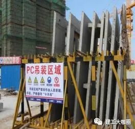
The lifting zones should be enclosed with fences and marked with clear warning signs. Safe personnel pathways must be established within the yard. When storing components, the embedded lifting parts must be positioned to avoid obstruction and allow easy access for lifting.
Vertical prefabricated components require cushioning at the base to absorb downward force. Horizontal components should be supported with wooden pads underneath, facilitating lifting and providing protection.
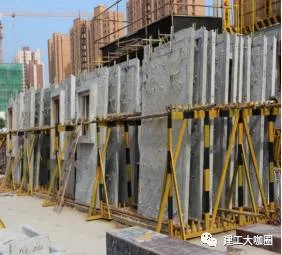
Prefabricated exterior wall panels should be placed in or against stacking racks designed with sufficient load capacity and rigidity. The outer surface must never be used as a support surface, and weak parts of the components should be protected. When wall panels lean against each other, triangular steel channel brackets meeting stiffness requirements should be used, balanced with the outer surface facing outward and tilted between 5° and 10°. Support points should be at both bottom ends, with flexible materials used for padding. Temporary fixing measures are necessary after stacking.
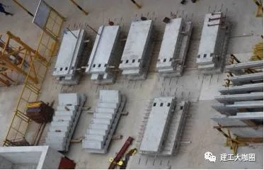
Prefabricated interior wall panels, composite panels, columns, and beams should be stacked carefully. Composite panels should not exceed six layers, with four evenly sized wooden blocks used as padding. The height of these blocks must exceed the exposed stirrups to prevent panel damage. Columns and beams should not be stacked more than two layers, with support pads placed underneath and between layers. These pads must be flat, vertically aligned, and placed on a solid foundation. If stacking exceeds these limits, the bearing capacity of supports and foundation must be verified.
Figure 2-9 illustrates on-site stacking of prefabricated interior wall panels.
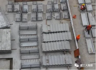
Balcony panels and stairs require four packs of yellow sand or wooden pads underneath to level height differences and prevent tilting or sliding. Air conditioning panels are stored horizontally to facilitate railing welding during construction.
Figure 2-10 shows on-site stacking of prefabricated air conditioning panels and stairs.
Irregular components must be stacked according to the construction plan and site conditions. Parapet wall components with irregular shapes should be laid horizontally as single pieces.
Prefabricated building
Note: The copyright of the above materials belongs to Shanghai Jianfeng College and Shanghai Construction Second Construction Group.


Must log in before commenting!
Sign Up