Abstract:
In China, few super high-rise buildings utilize the “internal pouring and external hanging” system. This method involves prefabricating enclosure components that are challenging to cast on-site within factories. These components are then transported to the external hanging installation nodes where they are poured on-site together with the internal vertical main load-bearing structural elements. This approach effectively prevents water seepage in external walls and enhances construction efficiency.
This article presents key technologies related to the “internal pouring and external hanging” system for super high-rise prefabricated buildings. Topics include horizontal and vertical node connection techniques for prefabricated external hanging wall panels, waterproofing methods, seismic and wind resistance strategies, on-site installation accuracy and collision prevention, as well as construction organization and management. These insights are grounded in the sensitive response of super high-rise buildings to seismic and wind loads and offer valuable references for adopting this system in China.
Keywords: Super high-rise buildings; Prefabricated buildings; Internal pouring and external installation; Prefabricated external wall panel
1. Introduction
Industrialized construction methods bring significant benefits such as resource savings, labor reduction, and improved quality. According to professional studies, these methods can reduce energy consumption by 23%, water use by 79%, formwork use by 81%, and construction site waste by 20%. Consequently, promoting prefabricated construction is essential for modernizing China’s traditional construction industry.
Currently, prefabricated shear wall structures are mainly constructed using four methods:
(1) Assembled integral shear walls, where precast shear wall bodies are used with cast-in-place edge components;
(2) Double-sided laminated shear walls, prefabricated on both inner and outer sides with cast-in-place cores;
(3) Single-sided composite shear walls, prefabricated on the outer side with cast-in-place inner sides;
(4) Internal pouring and external hanging, involving cast-in-place load-bearing main structural components and factory-prefabricated non-load-bearing enclosure components installed externally and poured together at connection nodes.
While the first three methods suit general high-rise buildings, the internal pouring and external hanging system is ideal for super high-rise buildings. It maintains compliance with structural design codes by combining cast-in-place main load-bearing structures with prefabricated external walls installed on-site, ensuring overall structural integrity.
This paper introduces key technologies for this system, covering design, production, and construction processes, and incorporates design practices from Hong Kong and mainland China, considering the seismic and wind sensitivity of super high-rise buildings.
2. Flexible Connection Node Technology
Due to their height and number of floors, super high-rise buildings experience significant horizontal seismic and wind forces. Prefabricated external wall panels must resist these horizontal loads in addition to vertical loads. To address this, connection nodes utilize the following techniques:
Establishing a rational load transfer path between the main structural components and non-load-bearing elements:
Typically, vertical loads are transferred through anchoring protruding steel bars at the top of prefabricated panels into the main structure’s load-bearing components. Horizontal seismic and wind loads are managed by integrating steel bars at both ends of prefabricated panels into the main vertical structural components to create a unified system. This “pre-installation method” constructs prefabricated exterior wall panels first, followed by casting beams and slabs. The steel bar connections at panel ends are designed to transfer shear forces without bending moments, achieving a “flexible connection” that reduces stress on the main structure.
Finite Element Analysis for Complex Geometries:
For prefabricated components with intricate spatial shapes, finite element software is used for detailed stress analysis. Figure 1 illustrates a prefabricated convex window model from a super high-rise coastal project with a seismic intensity of 7 degrees, analyzed using Abaqus software. Results highlight increased forces at the convex window’s top ends, prompting reinforcement of outward-extending steel bars in those areas.
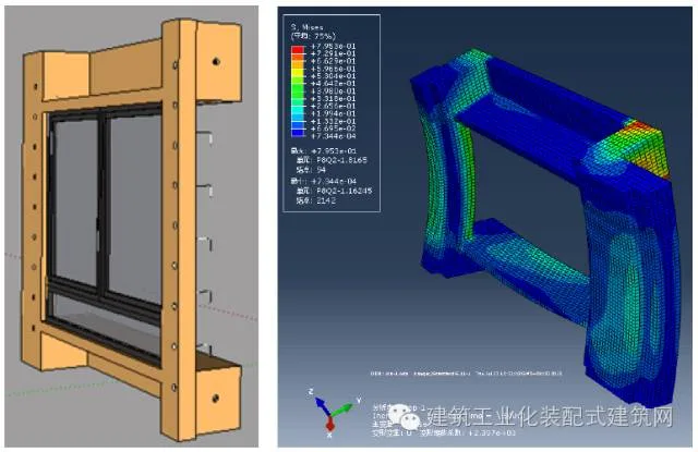
Figure 1: Force analysis model of a prefabricated convex window
3. Waterproof Design Techniques
Horizontal joints of external wall panels utilize a boot foot joint with tongue and groove structures, as shown in Figure 2. Vertical joint surfaces undergo water washing or flower sweeping treatments to improve tightness. Additionally, a water stop groove serves as a secondary waterproof barrier, as depicted in Figure 3. These multiple waterproofing routes effectively prevent water seepage through external walls.
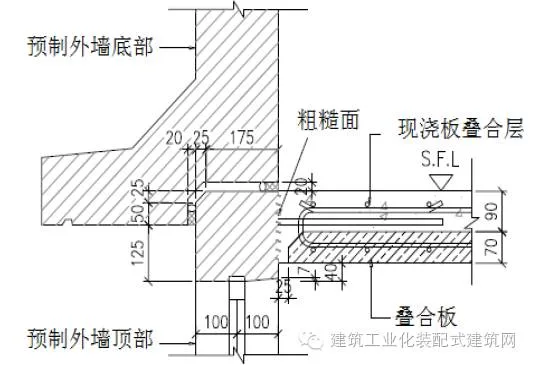
Figure 2: Horizontal joint nodes and waterproof structure of external wall panels
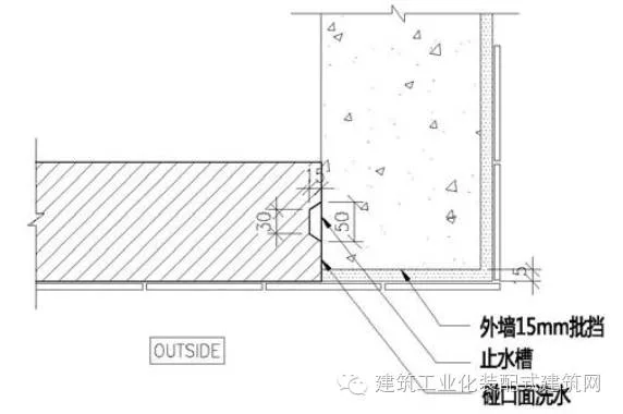
Figure 3: Vertical joint nodes and waterproof structure of external wall panels
To prevent water leakage around doors and windows, these elements are prefabricated integrally with the exterior wall in the factory, embedding connectors within the components to ensure waterproofing through concrete construction. Balcony design maintains the balcony’s elevation below the indoor floor level, with the bottom structural size of prefabricated exterior wall doors not less than 125mm to ensure structural stiffness and prevent deformation, meeting waterproofing standards. On the top floor, cast-in-place structures wrap around the top of prefabricated walls, ensuring seamless integration and waterproofing.
4. Wind Resistance Technology
When prefabricated external wall panels lack adjacent structural walls or columns, or their spans are large, wind loads may lift panels off beams, especially in super high-rise buildings. To prevent this, wind code devices fix panels securely without transferring their load to lower structural components.
The upper protruding steel bars of panels anchor into beams or slabs, the right side connects to shear walls, and the left connects to structural columns or non-structural walls. The left and lower sides act as free ends, while the right and upper sides serve as simply supported flexible connections. At the free ends, wind code devices are installed, as illustrated in Figure 4.
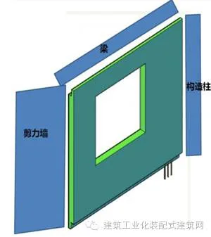
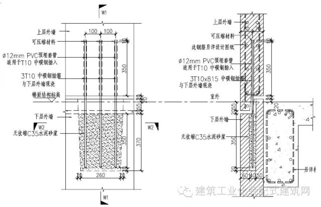
Figure 4: Wind code device position and structure
Wind codes secure panels to lower beams, while PVC pipes around the steel bars at the wind code’s upper end prevent force transmission to the beam. For super high-rise buildings, wind codes are required at one end of non-structural walls and mid-span positions of panels with larger spans. Calculations show that for 150mm-thick panels with floor heights around 3.5m and building heights near 100m, spans exceeding 5m lack sufficient stiffness to resist wind loads without wind codes.
The placement and quantity of wind code devices depend on panel spans and anchoring methods. Functionally similar to bolts, these devices primarily resist shear forces from wind. Their steel reinforcement type is determined by calculations, and construction typically involves post-grouting or post-pour concrete around the devices. Continuous optimization improves construction efficiency.
5. Quality Control Technologies
Quality control employs the PASS (Performance Assessment Scoring System) during construction. PASS calculates an overall quality score based on averaged monthly scores over the previous year, multiplied by a fixed coefficient. An independent review team conducts quarterly inspections: two months focusing on structural and interior finishes, one month on safety. This system ensures objective quality assessment.
Before mass production, BIM model simulations and factory rehearsals of installation processes allow visualization of project results, preventing errors such as component size mismatches or connection conflicts. These rehearsals also provide valuable training for industrial workers.
6. Installation Accuracy Control Technology
Prior to installation, dimension lines such as centerlines and elevations are marked on components and supporting structures according to design. Embedded parts and connecting steel bars are verified against design documents.
Installation begins by securing one end of a diagonal brace to the ground or floor panel and fixing the bottom of a seven-character code there. After lifting components into position, they are fixed to the corresponding seven-character code points. Adjustments to the rotation device of support rods calibrate component straightness, while nuts on the seven-character codes fine-tune horizontal and vertical alignment (Figure 5).
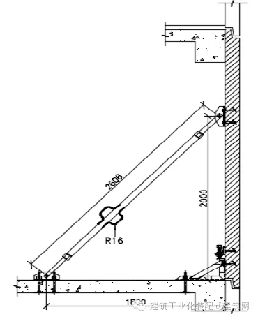
Figure 5: Installation details of prefabricated exterior wall panels
When upper and lower prefabricated exterior walls differ in thickness and lack alignment lines, achieving level alignment using only the seven-character code is difficult. Angled channel steel auxiliary devices are added to the lower exterior wall, allowing the upper wall to be lifted inside the auxiliary device for easier alignment and installation (Figure 6).
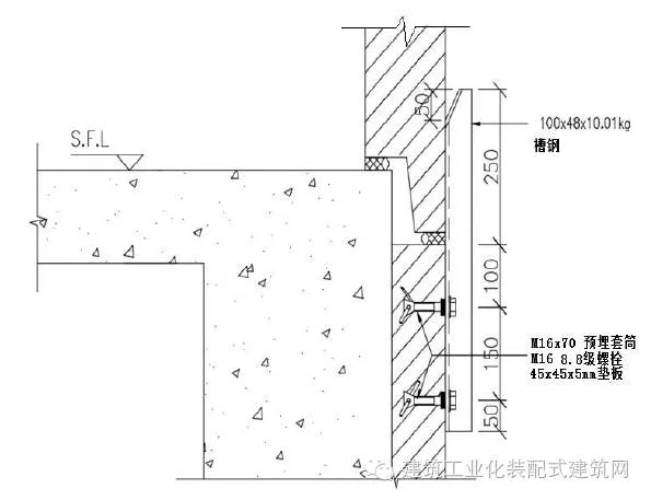
Figure 6: Auxiliary device using angled channel steel
7. Anti-Collision Technology for Steel Bars
Steel bar collisions can occur between prefabricated components or between components and cast-in-place structures, disrupting installation. Design must consider these collisions by staggering steel bars of cast-in-place structures relative to protruding bars of prefabricated components. Factory rehearsals and sample installations help identify and resolve potential clashes.
When two adjacent prefabricated exterior wall panels connect to a shear wall, dense steel bars at nodes often collide. To avoid this, outward-extending steel bars on adjacent components are bent outward or inward respectively, while vertical and horizontal shear wall bars are staggered to prevent interference (Figure 7).
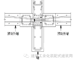
Figure 7: Detailed connection of adjacent exterior wall panels
Similarly, when connecting laminated and fully prefabricated floor slabs, protruding steel bars are prone to collision, potentially preventing connection and affecting concrete casting. Design solutions include bending protruding steel bars upwards inside components and overlapping them with additional steel bars to ensure tight connections, as shown in Figure 8.
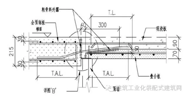
Figure 8: Large sample of adjacent floor slab connections
8. Construction Organization and Management Techniques
Because non-structural prefabricated components are factory-produced, the construction workflow is streamlined, greatly benefiting site organization. The main steps include:
1. Hoisting and installing prefabricated components;
2. Binding cast-in-place steel bars;
3. Assembling large steel/aluminum formwork supports;
4. Casting concrete.
Due to the speed and short duration of hoisting, it can proceed concurrently with other tasks without causing delays. Effective management of cast-in-place processes remains crucial. This involves organizing labor teams logically, dividing construction sections by workflow and spatial zones, enabling a “four-day per floor” construction cycle. For example, day one involves hoisting and installing prefabricated components while tying shear wall steel bars; day two includes formwork installation and floor steel bar tying; day three allows concrete pouring in completed sections.
9. Project Applications
The internal pouring and external hanging technology has broad applicability and high potential for promotion. Two notable projects demonstrate its use:
The Kai Tak 1A project in Hong Kong comprises six residential towers of 35-41 floors, a shopping mall, and underground parking (Figure 9). Residential buildings use internal pouring and external hanging shear wall structures, with cast-in-place shear walls and approximately 40% prefabrication for non-load-bearing components. Prefabricated elements include exterior wall panels, composite floor slabs, stairs, and integrated bathrooms. The prefabricated volume reaches 17,000 m³, leveraging standardized design to reduce costs and boost efficiency.
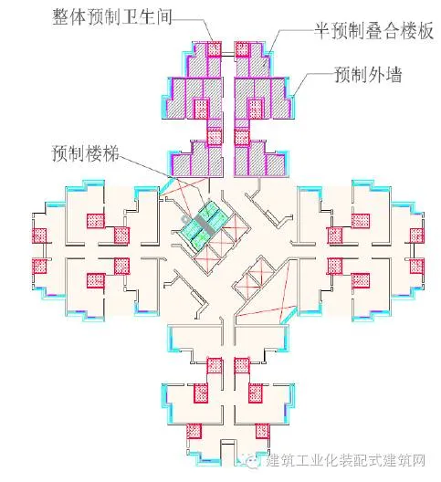
Figure 9: Standard floor plan of the Kai Tak 1A project
The Zhonghai Tianzhuan project in Shenzhen’s Luohu District consists of 11 towers, including two super high-rise prefabricated shear wall structures at 148m (46 floors) and 126m (46 floors). The seismic fortification level is Class C with a structural safety rating of Class II, designed for a 50-year service life. According to Shenzhen’s residential industrialization regulations, prefabrication rates must meet minimum thresholds of 30% assembly and 15% prefabrication. The project optimizes costs by prefabricating convex windows, floor slabs, and stairs (Figure 10). Located in a seismic zone of intensity 7 and a coastal area, the project faces significant seismic and wind loads, requiring rigorous structural and component-level analysis.
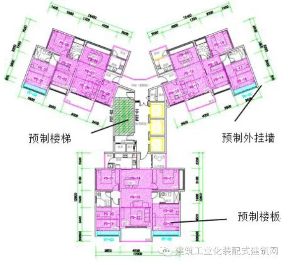
Figure 10: Standard floor plan of the Zhonghai Tianzhuan project
10. Conclusion
The “internal pouring and external hanging” system preserves the overall integrity of the load-bearing structure and simplifies external wall construction. Compared to other prefabricated shear wall systems, it offers superior cost-effectiveness. Given the high construction costs in the early stages of prefabricated building development, this method holds great promise for widespread adoption. Key takeaways include:
(1) Joint stress and waterproofing are critical to prefabricated building quality. Finite element analysis of a super high-rise building in a seismic zone demonstrates that panel ends experience higher stresses under seismic loads. Designing nodes and waterproof structures for horizontal and vertical joints ensures durability and watertightness.
(2) Wind code technology prevents prefabricated external wall panels from lifting under strong winds, making the system suitable for super high-rise applications.
(3) Component quality is vital. The PASS system ensures comprehensive quality control. BIM simulations and factory pre-installations prevent size errors and collisions while enhancing worker skills.
(4) Installation accuracy directly affects construction quality. Temporary installation systems effectively control panel alignment.
(5) Using staggered steel bar arrangements avoids installation collisions, preserving construction efficiency.
(6) Efficient construction organization and management enable a four-day floor construction cycle.
(7) Two exemplary super high-rise projects in Hong Kong and Shenzhen demonstrate the system’s successful application.
References:
Technical Specification for Prefabricated Concrete Structures – AI-BT_SC_1, China Architecture & Building Press, 2014
Mai Yaorong, “Evolution of Prefabricated and Prefabricated Construction Methods for Public Housing in Hong Kong,” Concrete World, 2015
Code of Practice for Prefabricated Concrete Construction – AI_S_SC_4, Buildings Department, 2004
Yee, Alfred A., “Design Consideration for Precast Prestressed Concrete Building Structure in Seismic Areas,” PCI Journal, Vol. 36, No. 3, May-June 1991, pp. 40-55
Note: The cover image features the exterior design of the Sea Sky Diamond, sourced from Sohu Focus.
You may also want to see:
– The project with the highest prefabricated assembly rate in South China has successfully entered the assembly construction stage – the first batch of prefabricated columns have been installed successfully
– Zhou Chong: Information Management Technology for Prefabricated Building Design Production Based on BIM-MES System
– The grand project of the G20 summit, admired by leaders worldwide, offers valuable lessons for all construction companies!
– The awarding ceremony of the academician and expert workstation of China Construction Technology was held in Beijing
– Dunhuang Miracle in the Desert: Prefabricated Construction + EPC Engineering General Contracting
– Heavyweight! The State Council once again clarifies the promotion of green buildings and prefabricated buildings


Must log in before commenting!
Sign Up