1. Application and Development of Urban Pipe Corridors
1.1 Introduction to Urban Pipe Corridors
Pipe galleries represent one of the most advanced infrastructure pipeline layouts worldwide. They are a growing trend in urban construction and development, offering an effective way to maximize the use of underground space. Modernizing urban infrastructure and optimizing the development and utilization of underground space through comprehensive underground pipe galleries has become a widely accepted goal both domestically and internationally.

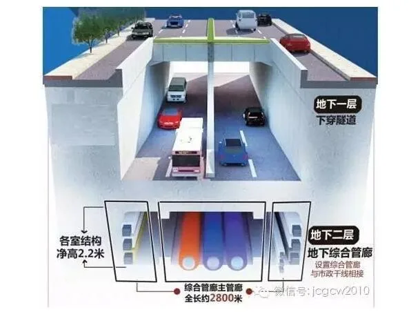
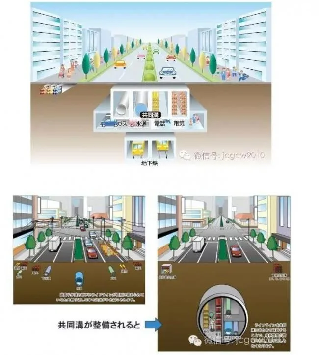
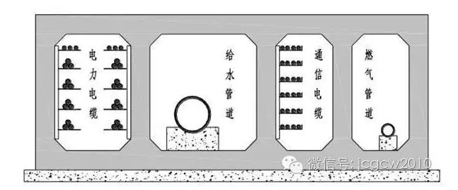
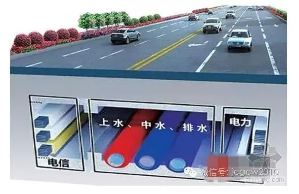
An urban pipe gallery is defined as a comprehensive underground corridor housing various municipal pipelines beneath a city. This tunnel space accommodates multiple pipelines such as electricity, communications, gas, water supply, heating, and drainage. It includes dedicated entrances and exits for personnel, pipeline access points, maintenance and lifting ports, as well as disaster prevention and monitoring systems. The pipe gallery serves as a new type of municipal public utility facility with unified planning, design, construction, and management.
1.2 Application of Urban Pipe Corridors
The concept of underground comprehensive pipe galleries originated in 19th-century Europe, with France being the first country to adopt this method. Since the establishment of the world’s first underground comprehensive pipe gallery system in Paris in 1833, nearly two centuries of development have followed.
France
Following a cholera outbreak in 1832, France recognized the critical role of urban public health infrastructure in controlling epidemics. In 1833, Paris began planning an urban sewer system that accommodated five types of pipelines: tap water (including drinking and cleaning water), telecommunications cables, compressed air pipes, and traffic signal cables. This was the earliest example of a planned and constructed comprehensive pipe gallery.
Germany
In 1893, Germany constructed a 450-meter-long comprehensive pipe gallery beneath the sidewalks of Kaiser Wilhelm Street in Hamburg. This gallery housed heating pipes, water pipes, electricity, telecommunications cables, and gas pipes, although it did not include sewers.
Spain
Spain initiated its comprehensive pipe gallery planning and construction in 1933. By 1953, Madrid launched the Service Comprehensive Pipe Gallery Plan, which evolved into the widely used system today. Investigations by municipal officials revealed that these galleries significantly reduced road excavations, eliminated road collapses and traffic congestion, and extended road lifespans. These projects demonstrated both technical and economic success, leading to broader adoption.
Britain
In 1861, London built a comprehensive pipe gallery with a semi-circular cross-section measuring 12 meters by 7.6 meters. It accommodated water, sewage, gas, electricity, and telecommunications pipes, including supply pipelines connecting users. Over 22 such galleries exist in London, funded and owned by the City of London government, which leases them to pipeline operators.
Japan
Japan began constructing comprehensive pipe galleries in 1926, referring to them as “Tonggou” for promotional purposes. After the Great Kanto Earthquake, the Yaeyama Trench was built to revive the capital. Large-scale construction commenced in 1963 following the enactment of the Special Measures Law for Trench Construction. The common ditch, a legal road accessory, expanded from traditional pipelines to include heating and waste transport pipes, spreading from densely populated megacities to regional centers such as Sendai, Okayama, Hiroshima, and Fukuoka.
Countries like the United States, Canada, and Russia, despite their vast territories, have developed relatively complete shared communication systems over the past century. For example, New York City’s large-scale water supply system runs entirely through underground rock formations. Toronto and Montreal also feature advanced shared communication networks. Moscow has a 130-kilometer-long common ditch containing various pipelines except gas, though its cross-section is small and ventilation poor.
In 1991, Taiwan completed its first common ditch on Zhonghua Road in Taipei, coinciding with railway undergrounding projects. Over the past two decades, efforts to promote comprehensive pipe galleries have yielded more than 300 kilometers of such infrastructure.
Beijing
The first common ditch in mainland China was built in 1958 beneath Tiananmen Square. To avoid future excavation in this historic area, a comprehensive pipe gallery measuring 4.0 meters wide, 3 meters high, 7-8 meters deep, and 1.3 kilometers long was constructed to house power, telecommunications, heating, and other pipelines. In 1977, a similar but shorter gallery of about 500 meters was also built.
Tianjin
In 1990, a 50-meter-long tunnel, 10 meters wide and 5 meters high, was built to manage pedestrian paths, pipelines, and multi-track railway crossings at the new passenger station. Alongside, a 2.5-meter-wide comprehensive pipe gallery accommodated water supply, drainage, electricity, and cables, serving as a prototype for China’s pipe gallery systems.
Shanghai
By the end of 1994, the Zhangyang Road common ditch in Shanghai’s Pudong New Area was completed, marking a milestone in domestic pipe gallery construction. Existing and rebuilt comprehensive pipe trenches in China include power cables, telecommunications cables, water supply, heating, and drainage pipelines. This represents the first large-scale operational comprehensive pipe gallery in the country.
Guangzhou
In late 2003, Guangzhou University Town saw the construction of an underground comprehensive pipe gallery extending 17.4 kilometers with a cross-section of 7 meters by 2.8 meters. This remains the longest and largest operational pipe gallery in China.
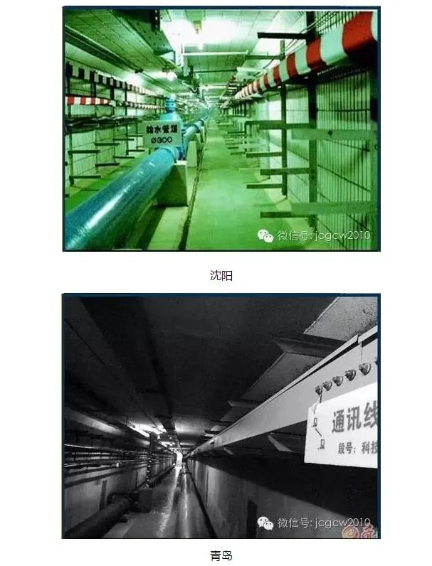
Other major cities such as Shijiazhuang, Kunming, Shenyang, Qingdao, Wuxi, Zhuhai, Wuhan, and Shenzhen are actively planning and constructing underground comprehensive pipe gallery projects.
1.3 Basic Types of Urban Pipe Corridors
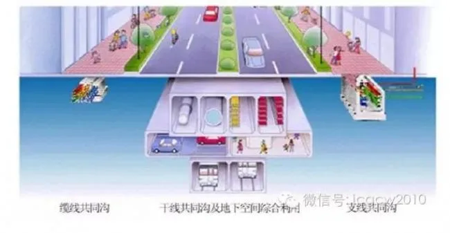
Urban comprehensive pipe galleries can be categorized into three types based on the pipelines they accommodate: mainline comprehensive pipe galleries, branch line comprehensive pipe galleries, and cable comprehensive pipe galleries (or cable trenches).
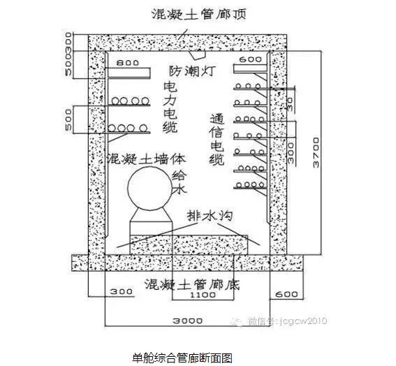
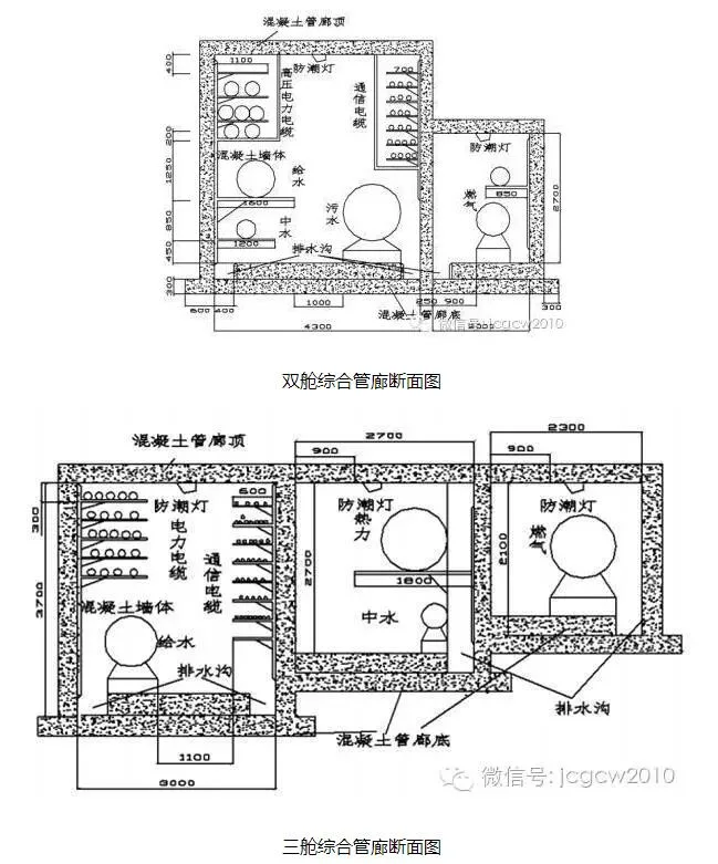
Main Comprehensive Pipe Gallery
The mainline comprehensive pipe gallery is typically located beneath the road center and serves as the distribution hub to branch galleries. It houses primary pipelines including communication, cable television, electricity, gas, and tap water. Some galleries also include rainwater and sewage systems. These galleries are characterized by large cross-sectional dimensions, deep soil cover, system stability, high capacity, and stringent safety, maintenance, and testing requirements.
Branch Comprehensive Pipe Gallery
Branch galleries connect main galleries to end-users and are generally located beneath sidewalks on both sides of the road. They mainly accommodate direct service pipelines such as communication, cable TV, electricity, gas, and tap water. The cross-section tends to be rectangular. These galleries are smaller in size, cost less to build, and offer high system stability and safety.
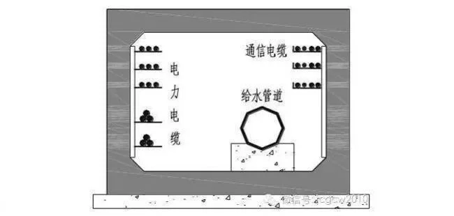
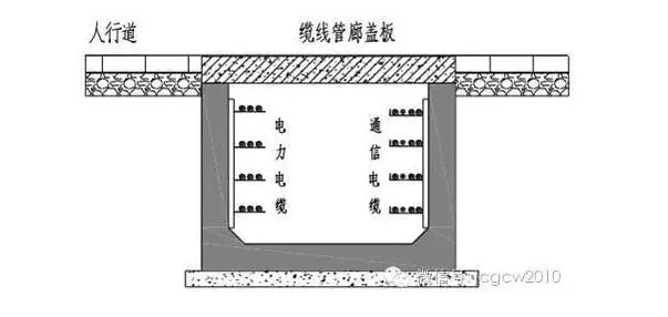
Cable Comprehensive Pipe Gallery
Cable galleries are typically buried beneath sidewalks and contain pipelines such as power, communication, and cable television lines that supply end-users directly. These galleries are characterized by small cross-sections, shallow burial depths, low construction costs, and the absence of ventilation or monitoring equipment, making maintenance and management relatively simple.
Cross-Section Shapes: Most galleries feature rectangular or circular cross-sections, designed according to pipeline types, quantities, construction methods, underground space, and local economic factors.
(1) Rectangular Cross-Section
Rectangular cross-sections offer advantages such as lower construction costs, higher space utilization, easier maintenance, spatial segmentation, and convenient pipeline installation. This type is typically used in open areas like new development zones and newly constructed roads.
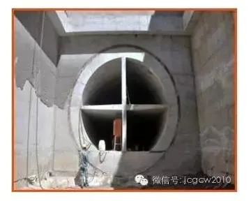
(2) Circular Cross-Section
Circular cross-sections are generally used for branch line and cable line municipal comprehensive pipe galleries.
Ancillary Facilities
Key ancillary systems in pipe gallery planning include ventilation, lighting, power distribution, fire protection, drainage, harmful gas monitoring, alarm, identification, monitoring management systems, and other equipment as required by authorities.
1.4 Development Prospects of Urban Pipe Corridors
Comprehensive pipe galleries have been prioritized as key infrastructure projects in the country’s 13th Five-Year Plan.
In 2015, the State Council issued the “Guiding Opinions on Strengthening the Management of Urban Underground Pipeline Construction,” initiating pilot projects in 36 large and medium-sized cities. The goal is to build internationally advanced underground comprehensive pipe galleries by 2020, reducing repeated road excavations (“road zipper” problem), enhancing pipeline safety and disaster resistance, eliminating overhead spider web lines on major streets, and improving urban landscapes.
On March 2, 2016, the Ministry of Finance announced central financial support for underground comprehensive pipe gallery pilot projects, jointly led with the Ministry of Housing and Urban-Rural Development.
2. Introduction to Main Construction Technologies for Urban Pipe Corridors
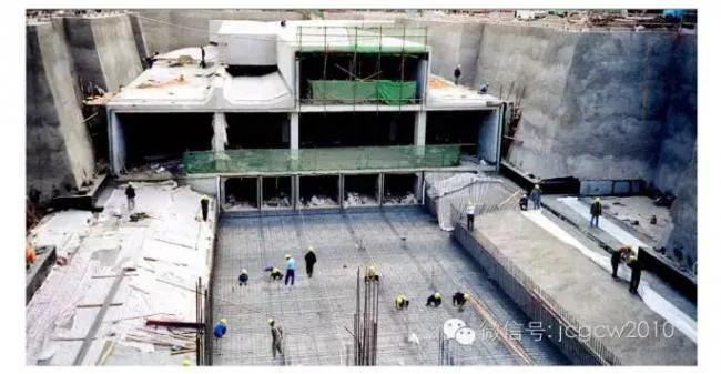
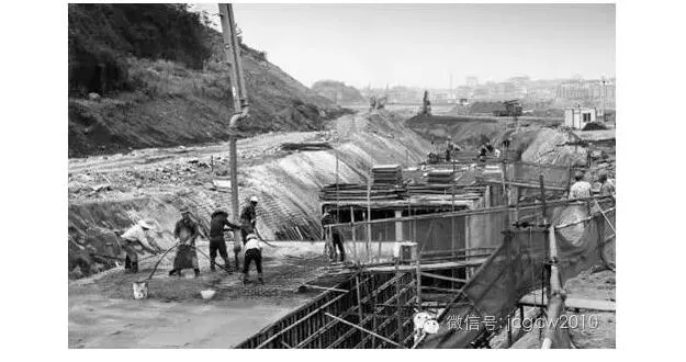
2.1 Open Cut Cast-in-Place Concrete Comprehensive Pipe Gallery
This is the most commonly used construction method for comprehensive pipe galleries. It supports large-scale operations by dividing the project into multiple sections, accelerating progress. Advantages include low technical difficulty, relatively low cost, and assured construction quality. The main drawback is the need to interrupt traffic during construction.
On flat sites without nearby buildings requiring protection, excavation and pipeline laying are performed during road construction. Large excavation methods with (deep) well-point dewatering are employed. This approach offers convenient construction without the need for enclosure structures, short build times, suitability for mechanization, and low cost. However, it involves large excavation volumes and high backfilling requirements.
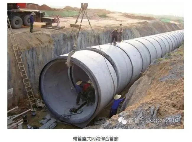
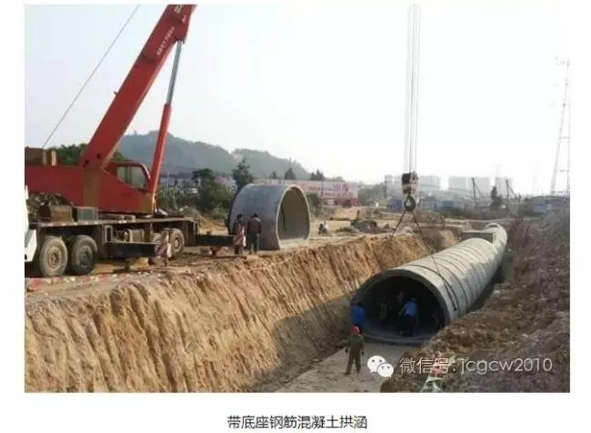
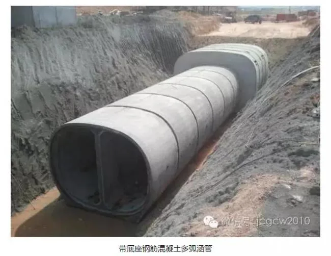
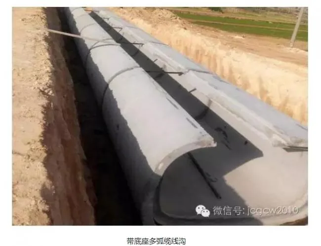
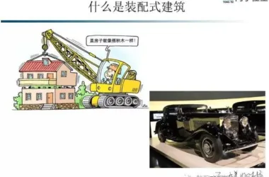
2.2 Prefabricated Assembly Method with Open Excavation
This advanced construction method is common in developed countries. It requires large-scale prefabrication plants, heavy transportation and lifting equipment, advanced technical skills, and higher project costs. Key prefabricated components include comprehensive pipe galleries with pipe seats, reinforced concrete arch culverts with bases, multi-arc reinforced concrete culverts with bases, and multi-arc cable trenches with bases.
Compared to traditional methods, prefabricated concrete culvert assembly ensures better quality, shorter construction periods, reduced costs, and energy and environmental benefits.
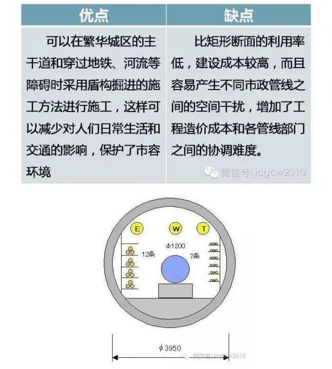
2.3 Shield Tunneling Construction Method for Comprehensive Pipe Galleries
Shield tunneling is used to build tunnels in soft soil with shield protection. This method involves excavation, material transport, lining assembly, joint waterproofing, and grouting under shield protection, alongside managing groundwater discharge and ground settlement. It requires advanced technical expertise and comprehensive management.
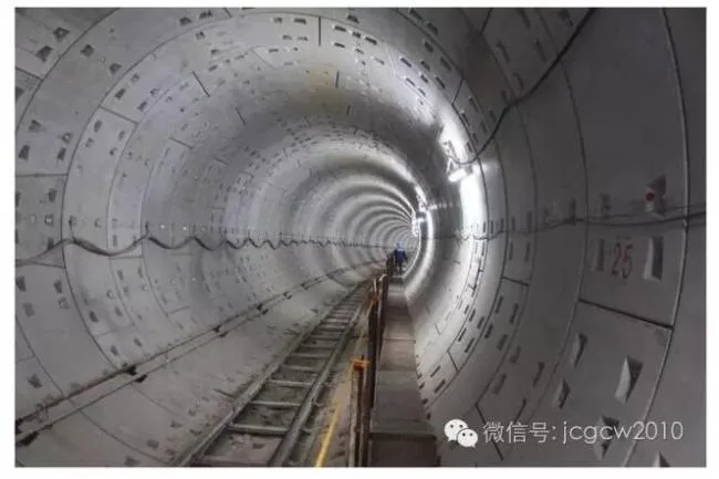
Benefits of shield tunneling include high mechanization, simple organization, easy management, construction safety, speed, excellent structural quality, minimal and controllable settlement, water-bearing formation capability without dewatering, small site footprint, and minimal environmental impact. It is especially suitable for tunneling near or beneath existing buildings and structures. Investment control is easier. Drawbacks include limited adaptability to engineering changes, high equipment costs, difficulty controlling settlement in shallow soil, and challenges with small curve radii. The use of shield tunneling machines in urban pipe gallery construction has been increasing.
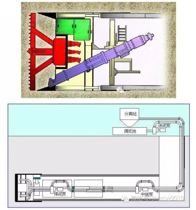
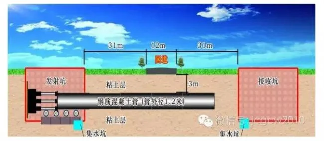
2.4 Top Pipe Construction Method for Comprehensive Pipe Galleries
Developed after shield tunneling, top pipe construction avoids surface excavation and can cross highways, railways, rivers, buildings, underground structures, and other pipelines. It uses hydraulic thrust cylinders and relay pipelines to push tool pipes or tunneling machines from a working well to a receiving well, simultaneously burying pipelines behind the machine, enabling non-excavation underground pipeline installation.
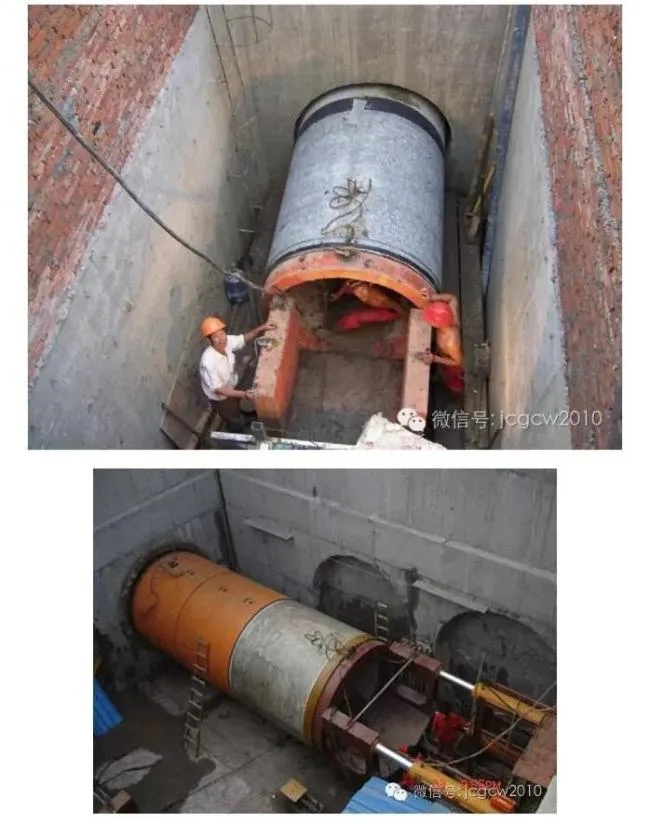
This method is especially suitable for non-excavation installation of medium to large diameter pipes. It offers economic, efficient, and environmentally friendly solutions. Advantages include no surface excavation, no demolition or damage to surface structures, minimal environmental impact, no effect on pipeline segment deformation, time savings, safety, and cost-effectiveness.
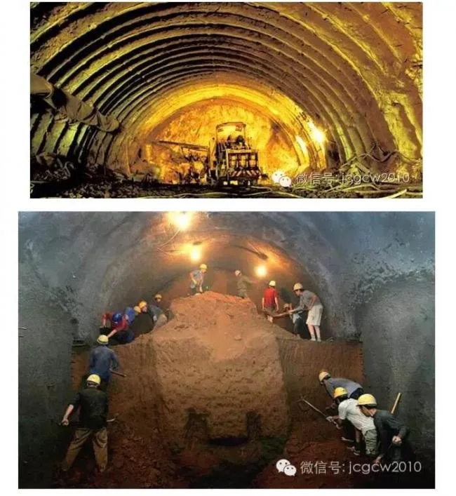
2.5 Conventional Concealed Excavation Construction Method
This method follows the New Austrian Tunneling Method principles, where the initial support bears basic loads and the secondary lining acts as a safety backup. Both supports share special loads. For shallow buried tunnels, multiple auxiliary construction techniques provide advanced support, improve surrounding rock stability, and mobilize its self-supporting capacity. Different excavation methods are used with timely support and sealing to form a joint support system with the surrounding rock. Throughout construction, monitoring, feedback, and optimized design ensure no collapse, minimal settlement, and safe construction, forming comprehensive support technologies.
2.6 Anti-Leakage Measures for Comprehensive Pipe Galleries
In areas with high groundwater levels, preventing seepage and leakage in underground structures is challenging. While some groundwater intrusion may not cause severe issues, it increases drainage facility usage and indoor humidity, reducing the lifespan of pipelines and monitoring equipment.
Anti-seepage design combines discharge, interception, and blocking strategies, balancing rigidity and flexibility, adapting to local conditions, and applying comprehensive management.
To control deformation, the length of culvert sections should be maximized to reduce deformation joints, which are placed between sections with shear keys to minimize relative settlement.
Key waterproofing areas include deformation joints, construction joints, ventilation openings, access points, entrances, and reserved ports. Deformation joints use composite waterproofing with buried rubber waterstops combined with external waterproof layers. Rubber waterstops are installed inside joints, treated with low-foaming plastic boards and polysulfide sealant. Construction joints, being weak points, should be minimized.
2.7 Comprehensive Pipe Gallery Node Treatment
Node processing is critical in design and construction, covering intersections (including T-junctions), river crossings, important underground structures (subways, elevated road foundations, pedestrian tunnels), and existing large-diameter rainwater and sewage pipelines.
At intersections, ensuring maintenance access complicates trench design. These nodes function like pipeline interchanges and may be designed as double-layer structures or enlarged plans for connectivity. When crossing roads, vehicle load impacts on the structure must be considered.
For river crossings and important underground facilities, decisions on passing above or below depend on relative elevation and location.
3. Examples of Urban Pipe Gallery Application Projects
3.1 Shanghai Zhangyang Road Joint Ditch
China’s earliest pipe gallery dates back to 1958, but the true milestone is the Zhangyang Road joint ditch in Shanghai’s Pudong New Area, completed in 1994 with a total investment of 300 million yuan. This 11.125-kilometer reinforced concrete rectangular structure runs beneath sidewalks from Pudong South Road to Jinqiao Road. It consists of separate chambers for electric power and gas.
The power chamber contains a central water supply pipeline with brackets for power and communication cables. The gas chamber houses gas pipelines separately. Safety features include drainage, ventilation, lighting, communication, CCTV monitoring, fire detection and alarms, combustible gas detection, oxygen monitoring, and a central data acquisition and display system. This was China’s first large-scale dual-side distribution pipe common ditch built on soft soil and the first to include flammable gas pipelines.
3.2 Gaobeidian, Asia’s Leading Thermal Engineering Project
Constructed using open excavation, the foundation pit employs row piles and anchor rods for support. Due to the dense pipelines, the pipe gallery requires an effective drainage system to manage leaks and accumulated water. A single-sided drainage ditch inside the gallery channels water to external drainage pipes. Pedestrian walkways prevent disruptions from water accumulation.
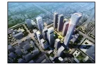
3.3 Zhongguancun West District Comprehensive Pipe Gallery, Beijing
Completed in 2006, this underground gallery integrates multiple municipal pipelines including tap water, rainwater, sewage, reclaimed water, power, communications, and natural gas within Zhongguancun Science and Technology Park’s core area. It is the park’s largest, most advanced investment project, covering 52 hectares above ground with a planned 1.3 million square meters of construction.
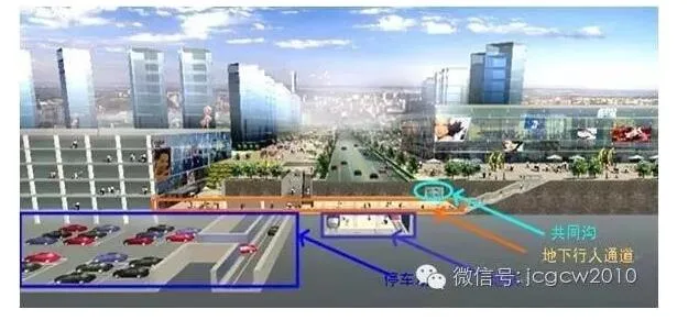
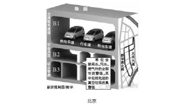
The project includes two main parts: the underground pipe gallery and underground space, with a total investment of approximately 1.7 billion yuan. The basement level serves as a transportation corridor, moving surface traffic underground and solving congestion. The second underground level features garages, commercial spaces, dining, warehouses, and property management. The third level houses public utility pipe galleries for gas, heat, electricity, telecommunications, and water. About 3 kilometers of main and branch pipelines transport utilities. This innovative design remains unique in China.
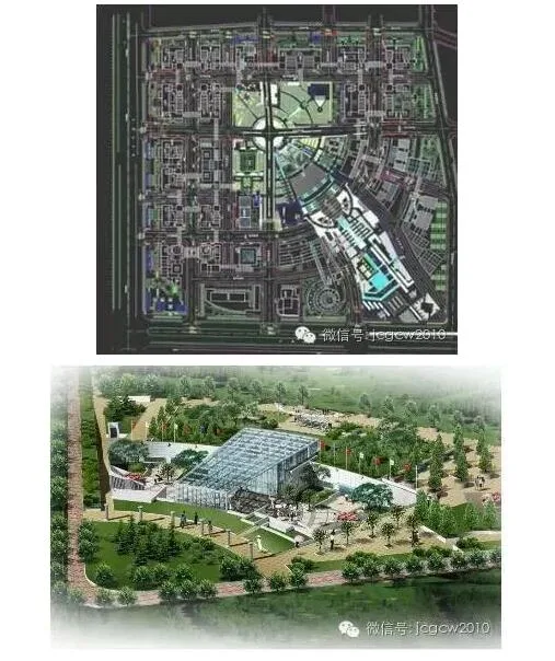
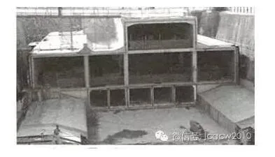
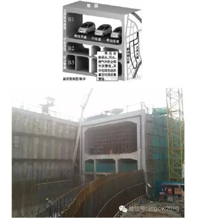
3.4 Comprehensive Pipe Gallery of Tongzhou Ring Tunnel
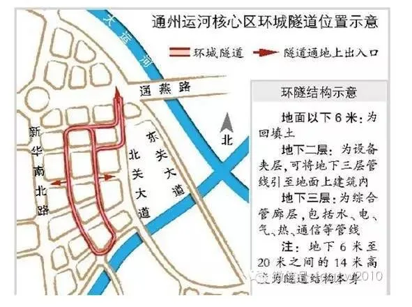
The North Ring Tunnel, located in the northern core area of Beijing’s Tongzhou Canal, spans 1.5 kilometers with four pairs of entrances and exits. It features a one-way, single-lane layout with multifunctional lanes on both sides, designed for 30 km/h speed. The structure comprises a lane level, a mezzanine for pipe gallery equipment, and a comprehensive pipe gallery.
This project received the Beijing Structural Great Wall Cup Gold Award.
3.5 Beijing CBD Underground Comprehensive Pipe Gallery
To enhance urban transportation, municipal facilities, and emergency shelter in Beijing’s CBD core, the underground infrastructure project consists of five subterranean floors, including six pipe galleries, a transportation hall, the main public space, and a cultural center.
The CBD core covers approximately 30 hectares bounded by Guomao Overpass, Guanghua Road, Jizhi Road, Jianguo Road Green Belt, and East Third Ring Road Auxiliary Road. Planned construction area is about 1.5 million square meters, housing office buildings, hotels, exhibition centers, and cultural facilities. Landmark buildings include “China Zun,” Beijing’s tallest at 528 meters. The CBD will feature Beijing’s largest underground public space, making it the deepest, largest, and most complex underground engineering project in the city.
3.6 Beijing Yuanda Road Power Pipe Gallery
Conclusion:
Urban pipe gallery construction is a defining trend in city development and an effective way to utilize underground space. In the near future, repeated road excavations (“road zipper” issues) will be significantly reduced, pipeline safety and disaster resistance will improve, overhead spider web lines will gradually disappear from major streets, and the urban landscape will be greatly enhanced. The frustrating experience of “watching water accumulate during rain” will become a thing of the past.


Must log in before commenting!
Sign Up