With the rapid urban development and continuous advancements in intelligent technology, the number of super high-rise buildings in cityscapes is increasing daily. BIM technology plays a vital role throughout the design, construction, and maintenance phases of these skyscrapers.
Project Overview
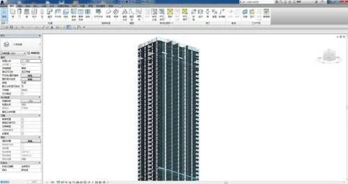
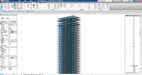
Shenzhen Zhongzhou Building is a premium commercial office tower that combines Grade A office spaces with supporting retail facilities. Situated in Plot 01-2 of the Gangxia Heyuan area on the eastern side of Shenzhen’s CBD South District, this project covers a total construction area of 76,700 square meters and reaches 200 meters in height.
The building consists of 40 floors above ground: floors 1-3 are dedicated to high-end commercial spaces including dining, with a three-story high lobby (including a mezzanine equipment floor at level 3a). Floors 4-15 house low-area offices; floor 16 serves as a refuge and equipment floor; floors 17-30 contain central area offices; floor 31 is another refuge and equipment floor; floors 32-39 accommodate high-area offices; and floor 40 is an equipment mezzanine. The rooftop core tube hosts building elevators, equipment rooms, and civil defense alarm rooms. Additionally, there are 4 underground levels primarily used for equipment rooms and parking.
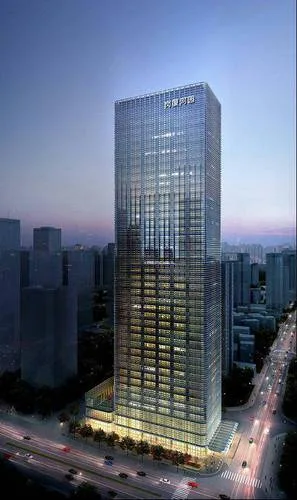
Overall rendering of Zhongzhou Building project
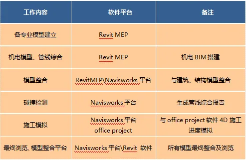
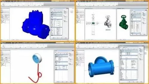
BIM Software Configuration Plan
Overall rendering of Zhongzhou Building project
Introduction to BIM Applications
1. Integration of architectural and structural disciplines into civil engineering is essential. This involves establishing, coordinating, and updating civil engineering models to ensure seamless collaboration between architectural and structural teams, preventing any conflicts. A grid and floor elevation system is created. The architecture team models structural walls, columns, steel beams, and columns across various floors and zones in cooperation with the structural team. Basic components such as partition walls, doors, windows, stairs, and rooms are modeled in the architectural domain. Exterior curtain walls and windows are also modeled across different building sections. After completing sub-models, these are linked to the respective floor models.
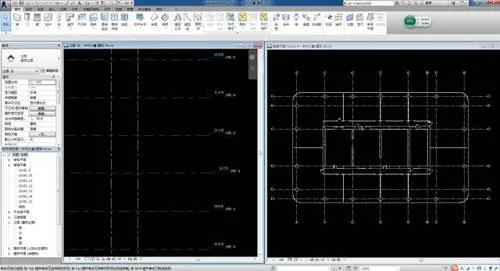
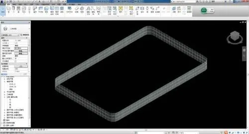
Establishment of standard floor grid and elevation system
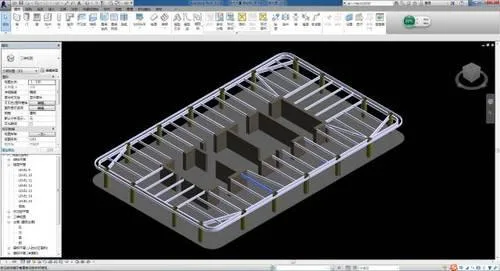
Modeling of 9-story standard floor structural walls and steel beam slabs
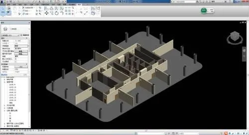
Models of doors, windows, and partition walls on the 9th standard floor
Outer curtain wall model for the 9th standard floor
Ground building model
2. The water supply, drainage, electrical, and HVAC disciplines are integrated into the mechanical and electrical specialty. HVAC is designated as the primary coordinating discipline to streamline design coordination. Together, the electromechanical model is created, coordinated, and updated to ensure timely integration and prevent conflicts among these disciplines.
Ground standard floor electromechanical system model
9th-floor electromechanical full system model
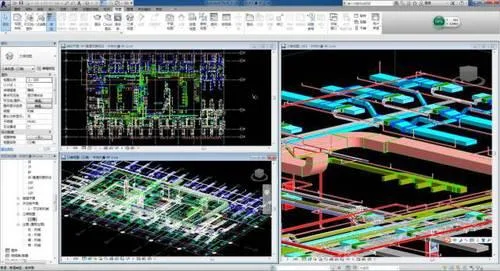
3. The 9th floor is selected as the sample floor for this super high-rise office building. After completing civil and electromechanical modeling, collision detection is automatically conducted using Navisworks, generating collision reports. BIM modeling and virtual visualization simulate critical components in 3D, allowing early detection and correction of design errors, which helps avoid cost overruns and delays.
9th-floor electromechanical sample model
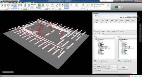
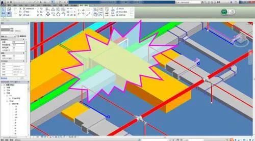
Navisworks collision detection on 9th-floor electromechanical model
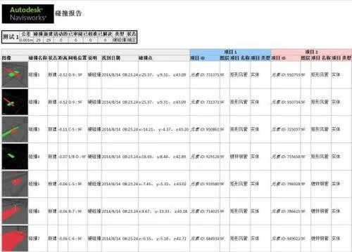
Collision detection report for 9th-floor electromechanical model
4. Real-time collaborative design optimization is performed by civil and electromechanical teams based on collision detection results to resolve conflicts and obtain cross-disciplinary approvals. 3D walkthrough simulations enhance work efficiency.
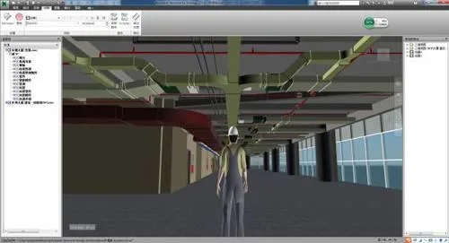
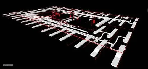
Full model walkthrough screenshot of 9th-floor electromechanical sample
5. BIM models are used to generate comprehensive mechanical and electrical pipeline diagrams, sectional views, discipline-specific drawings, 3D axonometric views, images, and animations. These help clearly communicate design intent and pipeline installation hierarchy to construction teams, reducing errors from misinterpretation.
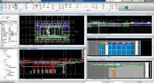
Pipeline sectional diagram of 9th-floor mechanical and electrical sample floor computer room
6. Construction progress is simulated by linking the BIM model with the project schedule, achieving 4D simulation. This visualizes construction interfaces and sequences, clarifies coordination among general contractors and various trades, and helps identify potential scheduling issues early.
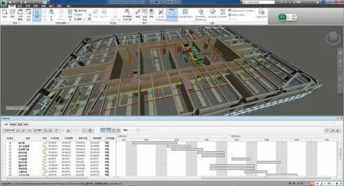
Construction progress simulation for 9th-floor electromechanical sample
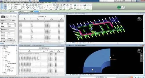
7. 5D quantity takeoff and material planning are performed using a parameterized information model. Utilizing Revit’s detailed schedules, standard floor pipeline quantities are calculated, providing reliable data for budgeting and cost estimation.
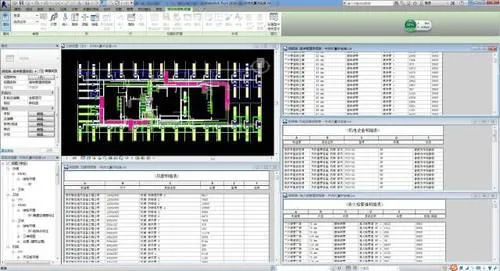
Quantity takeoff and material planning for 5D project on 9th-floor electromechanical sample floor
Sample electromechanical family library drawing
Summary of BIM Application
1. Collision Detection – Comprehensive Pipeline Layout Solutions
During the detailed mechanical and electrical system pipeline design, close collaboration with civil engineering, interior decoration, and other subcontractors is essential. Key principles include:
(1) Air ducts should be arranged at the top. When bridges and water pipes share the same height, they are separated horizontally; if aligned vertically, bridges go above water pipes. Space is comprehensively coordinated to avoid conflicts—pressure pipes defer to non-pressure pipes, smaller pipes defer to larger ones, and simpler construction avoids more complex routes. These are general guidelines but must be adapted to actual site conditions.
(2) The final pipeline drawings must show consistent positions, specifications, and elevations in both profile and plan views. Adjustments in profiles should be reflected in plans during coordination.
(3) Insulation thickness for water pipes, air-conditioning pipes, and ducts must be considered. Minimum clearances between cable trays, pipe exteriors, ducts, walls, and columns should be determined based on actual conditions. Pipeline slopes, operational and maintenance spaces must also be factored in. Distances between different pipelines must comply with design and construction codes.
(4) Understanding building structure details is critical—differences in building and structural elevations, thickness of concrete beams, column sizes, steel beam dimensions, and presence of diagonal supports must be accounted for. Decoration methods, ceiling heights, and wall construction techniques also influence pipeline layout.
Collision detection on the 9th-floor template model using Navisworks identified two clashes:
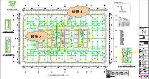
Pipeline collision locations on 9th floor ventilation and air conditioning duct system
Collision 1: Smoke exhaust system PY-04 on axis 6/B-C clashes with fresh air system XF-02 and exhaust system P-26 ducts.
Collision 2: Smoke exhaust system PY-05 on axis 7/D-E clashes with fresh air system XF-02 and exhaust system P-25 ducts.
A ventilation coordination meeting was promptly held to decide on corrective measures. Two options were considered, and the solution to flip the smoke exhaust duct upward was selected.
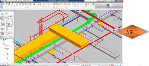
Collision resolution for ventilation and air conditioning duct system
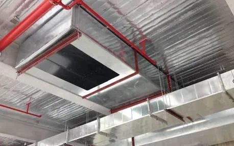
2. Virtual Construction Visualization (3D Simulation)
To overcome challenges in clearly communicating technical solutions, this project uses 3D simulation and virtual animation technology to visualize complex construction areas, anticipate problems early, and ensure quality.
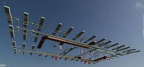
3D pipeline diagram of the 9th-floor mechanical and electrical model
3. Control of Reserved Openings in Walls and Floors
Civil engineering designs openings on different floors for mechanical and electrical systems and provides feedback and suggestions. The MEP team uses secondary development software (Hongye) to automatically detect and mark opening locations coordinated with walls and floors for HVAC, plumbing, fire protection, electrical, and other systems. Opening sizes are automatically determined based on discipline specifications. This information is transmitted via a collaborative server platform to civil engineering for batch processing and supports on-site construction.
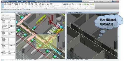
Reserved openings location map for mechanical and electrical coordination on the 9th floor
Comparison of reserved openings for ventilation ducts crossing walls on the 9th floor
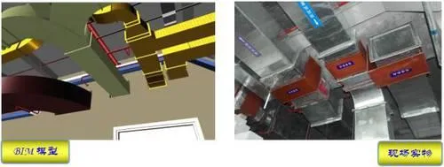
4. Factory Prefabrication and Processing of Ventilation Ducts Using BIM Models
Ventilation and air conditioning duct segments are divided, dimensioned, and numbered automatically based on collaborative designs across disciplines including water, heating, electricity, and structure. Prefabrication drawings and material lists are generated using Revit to advance factory prefabrication.
Prefabrication and material list for ventilation and air conditioning ducts on the 9th-floor sample
Using BIM models and 3D construction drawings instead of traditional 2D plans reduces onsite errors caused by misinterpretation. After preparing working surfaces, technical managers provide visual BIM-based instructions to pipeline installers. Construction drawings with pipe section numbers are distributed, and prefabricated pipe sections are delivered and installed sequentially according to these numbers. This allows workers to clearly understand installation positions and elevations, ensuring precise installation and quality control.
5. Mobile Terminal Model Management Based on BIM Cloud Service Platform
This project pioneers the use of a BIM cloud service platform with iPad mobile devices integrated into project management. Project members can access project information, perform model adjustments, and conduct conflict detection via desktop, mobile, and web interfaces. This enables BIM to support the entire lifecycle management from design through construction to maintenance.
Team members utilize Autodesk® Learn BIM 360 Glue software, seamlessly switching between Autodesk Navisworks and BIM 360 Glue for efficient workflows. This ensures full team participation in coordination, shortens coordination cycles, and provides tools for real-time model viewing and conflict detection anytime, anywhere — saving time and reducing costs during design and construction.


Can this drawing and model be downloaded? I want to learn