China Zun boasts a total construction area of approximately 427,000 square meters, with 108 floors above ground and 7 floors below. Once completed, it will surpass Guomao Phase III as the tallest building in Beijing. Situated in the heart of the Z15 plot within Beijing’s Central Business District (CBD), it faces Guomao Phase III, currently the tallest building in Beijing, to the west. The tower rises to a height of 528 meters and is planned to serve as the future headquarters of CITIC Group. Construction began around September 12, 2011, and was topped out by the end of 2016, with an estimated total investment of 24 billion yuan. Structural Design of China Zun
1. Project Overview
China Zun Tower is an iconic super high-rise located in the core of Beijing’s CBD, on the Z15 plot along the East Third Ring Road in Chaoyang District. The building’s total construction area is about 437,000 square meters, including approximately 350,000 square meters above ground and 87,000 square meters underground. The tower’s primary functions include office space, sightseeing, and commercial use.
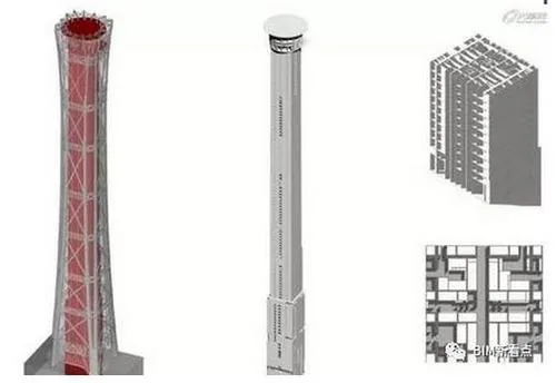
The building features 108 floors above ground and 7 underground, including some mezzanine levels, standing at 528 meters tall. Its footprint transitions smoothly from 78m × 78m at the base, narrowing to 54m × 54m mid-height, then slightly expanding to 59m × 59m at the top, resembling the shape of the ancient Chinese wine vessel “Zun”. An architectural rendering is shown in Figure 1.
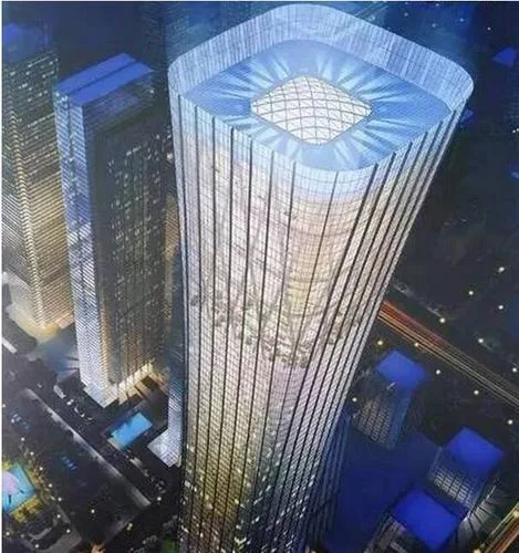
Figure 1: China Zun Building
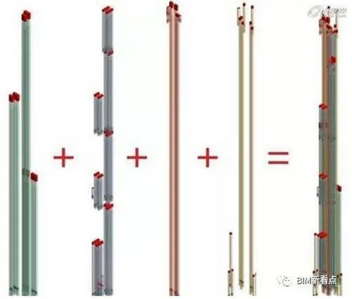
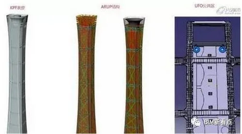
The main structural system combines an outer frame tube with a core tube. The outer frame tube consists of giant columns, giant slant supports, transfer trusses, and secondary frames. The giant columns are positioned at the tower’s corners, extending to the top and connecting with transfer trusses and giant slant supports at each section. Their bottom cross-section is polygonal, transitioning to rectangular multi-cavity steel tube concrete columns mid- and upper-levels.
Eight transfer trusses are located at equipment and refuge levels, fabricated from welded box sections. The giant slant supports run along each area’s outer skin and are also constructed from welded box sections. Secondary frames include gravity columns and outer ring beams, both welded H-shaped sections, designed to bear only gravity loads without contributing to lateral resistance.
2. Giant Outer Frame Tube Building – Structural Integration Design
2.1 Geometric Control Surface for Giant Outer Frame Tube
The China Zun’s exterior horizontal cross-section resembles a rounded square that smoothly expands and contracts along the height. The geometric control dimensions of the outer surface are illustrated in Figure 2.
The giant outer frame tube’s outer control surface adopts a segmented folded form, which effectively controls the gap between the frame and the building’s finished surface while simplifying structural fabrication.
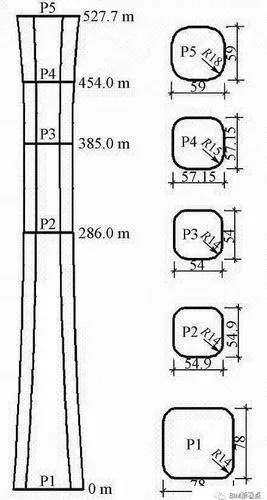
Figure 2: Geometric Control Dimensions of Outer Finish Surface
2.2 Outer Contour Generation of Giant Columns
The giant columns’ cross-sectional shapes vary systematically from the foundation level (-31.3m) up to the 106th floor (503.2m), with three distinct forms:
- Below the 7th floor (-31.3m to 43.15m): four octagonal sections, each about 63.9 m² in area.
- Between the 7th and 19th floors (43.15m to 98.65m): eight hexagonal sections, ranging from 19.5 to 21.3 m².
- From the 19th floor to the 106th (98.65m to 503.2m): eight rectangular sections, between 19.2 and 2.56 m².
There are 12 control turning elevations set for the giant columns, as listed in Table 1.
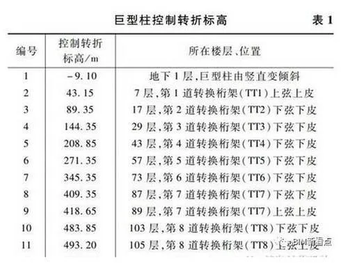
To optimize structural stress, the centroid of each giant column section at the 12 control elevations must lie within a vertical plane γ, angled at 27° to the horizontal or vertical planes, as shown in Figure 3.
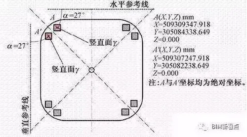
Figure 3: Cross-Section Schematic of a Giant Column
The final geometric positioning of the giant columns is based on three criteria:
- The centroid of the cross-section at each control elevation lies within plane γ.
- Corner points (P and P’) are continuous.
- The distance between each layer’s corner points and the outer finish surface is at least 500 mm (1,200 mm at the base).
The top-down positioning is illustrated in Figure 4.
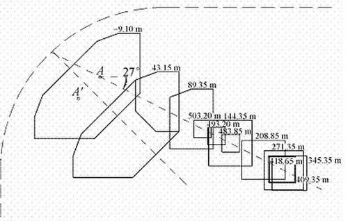
Figure 4: Top View Positioning Diagram of Giant Columns
2.3 Transfer Truss, Giant Slant Support, and Secondary Frame Generation
Once the outer control surface of the outer frame tube and the giant column contours are established, the positions of the transfer trusses, giant slant supports, and secondary frames can be precisely determined. This ensures seamless alignment and flush connections between components, facilitating fabrication and installation.
The tower is segmented into nine sections by eight transfer trusses, each following consistent geometric rules except for varying giant column inclinations. Figure 5 illustrates typical sections.
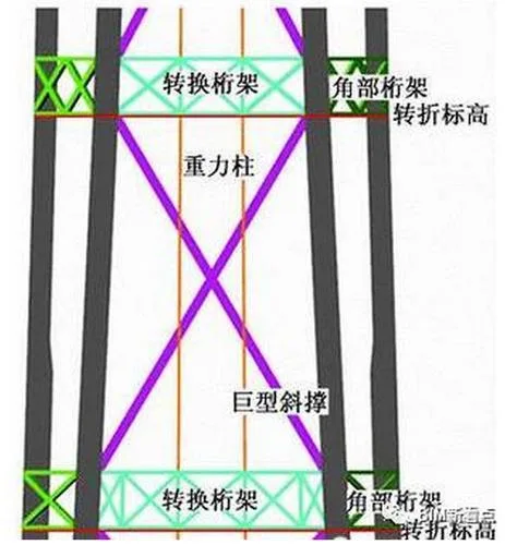
Figure 5: Typical Outer Frame Tube Section Diagram
The transfer truss, giant slant support, and secondary frame skin are flush with the outer frame tube’s external control surface. Horizontal stiffeners are installed at connection points between the transfer truss chord, giant slant support, and mega columns. The transfer truss chord sections are designed as parallelogram shapes (Figure 6a) instead of conventional rectangular sections (Figure 6b).
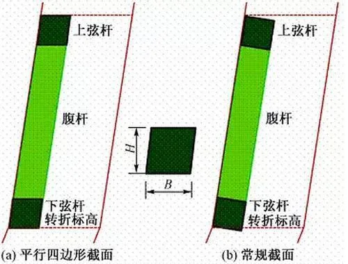
Figure 6: Conversion of Truss Section Generation Scheme
For example, a chord cross-section measuring 800 × 700 mm means the vertical height is 800 mm, and the horizontal width is 700 mm. The contour is defined by horizontal planes 800 mm apart and inclined planes parallel to the giant column’s outer control surface, spaced 700 mm horizontally.
Web members of the transfer truss follow similar section definition rules. For instance, a diagonal web member sized 900 × 700 mm is bounded by planes parallel to its axis and the outer surface of the giant column. Corner trusses follow these same generation rules for chord and web members.
The giant slant support section generation resembles that of the transfer truss web members, with a slight elevation offset at the intersection points of diagonal web members, chord members, and slant support axes (half the chord height), as shown in Figure 7.
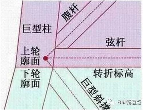
Figure 7: Node Positioning Diagram of Giant Slant Support
To avoid misalignment, the giant slant support cross-section—for example, 1600 × 900 mm—is defined by planes parallel to its axis and the lower wheel profile, enclosing the specified area.
The secondary framework’s spatial positioning mainly focuses on gravity columns, which align with the curtain wall glass grid. The curtain wall grid is based on the outer finish surface and horizontally divided into 128 equal parts at each floor’s reinforced slab elevation (Figure 8).
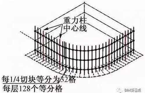
Figure 8: Gravity Column Centerline Positioning
Every sixth grid point on the outer surface is projected onto the upper and lower chords of adjacent transfer trusses, defining the gravity column centerlines. The outer contour of gravity columns is bounded by planes parallel to the axis and the outer surface of the outer frame tube. Gravity columns are constructed using welded H-shaped sections.
The cross-sectional generation of the entire outer frame tube structural components can be visualized as a structure exhibiting low shear stiffness but high bending stiffness, undergoing shear deformation under horizontal forces. The inclination of each section’s cross-section corresponds primarily to the outer completion surface inclination, as shown in Figure 9.
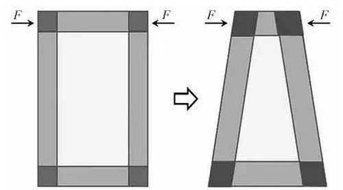
Figure 9: Principle of Cross-Section Generation
3. Pile Raft Foundation Design
The foundation system for China Zun is a pile raft foundation—an integrated assembly of foundation soil, piles, and raft slab working synergistically. The pile foundation is designed for a service life of 50 years, with durability estimated at 100 years. It meets Grade A design standards and Grade I safety levels. The seismic design aims to ensure pile strength under moderate earthquake elasticity and large earthquake non-yielding conditions.
There are three main pile types:
- P1: Located under the core tube and giant columns, with 1,200 mm diameter and 44.6 m length.
- P2: Positioned elsewhere under the tower, with 1,000 mm diameter and 40.1 m length.
- P3: Transitional piles between the tower and pure basement, with 1,000 mm diameter and 26.1 m length, serving as edge transitional piles.
The pile layout is depicted in Figure 10.
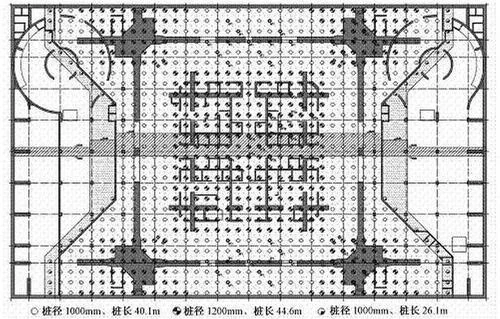
Figure 10: Pile Layout
Piles P1 and P2 bear on the first gravel layer and rounded gravel as the end bearing stratum, requiring at least 2.5 meters penetration. The pure basement area utilizes a natural foundation. All piles undergo grouting at the pile side and end for enhanced bonding.
The design philosophy emphasizes the pile raft’s interaction (Figure 11), carefully selecting the pile end bearing layer based on deformation control, and optimizing pile length, diameter, and spacing. Structural design considers the combined effects of the superstructure, raft foundation, and soil-pile system. Through extensive analysis, the initially planned settlement joint between the main tower and podium was removed, marking an innovative advancement in pile raft foundation design. The joint variable leveling concept is illustrated in Figure 12.

Figure 11: Schematic of Pile Raft Joint Interaction

Figure 12: Joint Leveling Design of Pile and Raft
After construction completion, single pile static load tests were conducted to verify bearing capacity. The Q-s curve is shown in Figure 13, confirming excellent pile foundation quality with 100% classified as Class I, providing a solid base for the design concept’s realization.
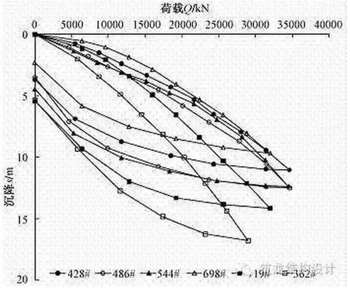
Figure 13: Q-s Curve of Engineering Pile
4. BIM Application in China Zun
1. Seamless Full-Scope Collaborative Design
China Zun is currently a BIM-enabled project developed by the Beijing Institute. Approximately 50% of the preliminary and construction drawings have been delivered to the client. All designers within the institute and collaborating companies work on a unified BIM platform, integrating 3D and digital technologies to enable true collaborative design under consistent standards. This large-scale project exemplifies BIM’s key advantage: a shared 3D platform that supports cross-team cooperation.
Moreover, BIM integrates the construction parties into this standardized system, ensuring BIM’s application throughout design and construction phases. The only comparable project is Shanghai Center, which also utilized BIM for design and construction. The approach requires designers to consider BIM model transformation to subsequent stages carefully. When properly implemented, BIM enhances design quality, efficiency, and facilitates smooth model transfer, positively impacting time and costs.

2. BIM Core Technology Throughout Design and Construction
At Beijing Institute, BIM is fully integrated within the design process. Design principles are established early, and designers build comprehensive BIM models accordingly. These models are continuously used to detect design issues, including spatial conflicts. BIM is not limited to handover but is an active tool throughout design iterations, generating multiple research models to help designers and construction teams anticipate and address potential problems early.
This process-focused BIM application distinguishes Beijing Institute’s approach, emphasizing BIM as a design service tool.
3. Challenges: Design Conversion During Construction
Despite technological advances, several factors limit BIM’s development during model transfer to general contractors. Many large-scale projects face compressed construction schedules, with design phases overlapping or abbreviated compared to international norms. Often, construction begins before design completion.
Under such constraints, implementing BIM can be time-consuming—sometimes 50% longer than traditional 2D methods—because incomplete designs prevent refined BIM models, rendering data less usable downstream.
Additionally, China’s architectural responsibility system differs from international standards, with architects bearing less authority and responsibility. The suitability of designers’ skills for BIM workflows is also a factor.
Past discussions affirm that BIM will advance architectural and engineering construction, with no inherent technical bottlenecks. Shanghai Center pioneered BIM in super high-rise projects, yet integration between design and construction parties remained a challenge. The China Zun project aims to overcome this hurdle.
4. Need for Refinement of BIM Implementation Standards
Currently, BIM in use is closely tied to design. As BIM evolves, developing comprehensive standards is a priority. Standards are dynamic, adapting alongside software and social environments.
Beijing Institute released internal BIM standards last year and updated them recently to better include design-related external factors, such as standardized residential buildings and seamless construction handoffs. These enhancements complement national standards, which remain high-level frameworks without detailed operational guidelines for enterprises.
Further refinement is essential. Ideally, detailed national BIM standards should be established sooner to avoid reliance on individual project agreements. Clear standards for software usage, data storage, and deliverables—akin to construction drawing standards—would streamline collaboration significantly.


Must log in before commenting!
Sign Up