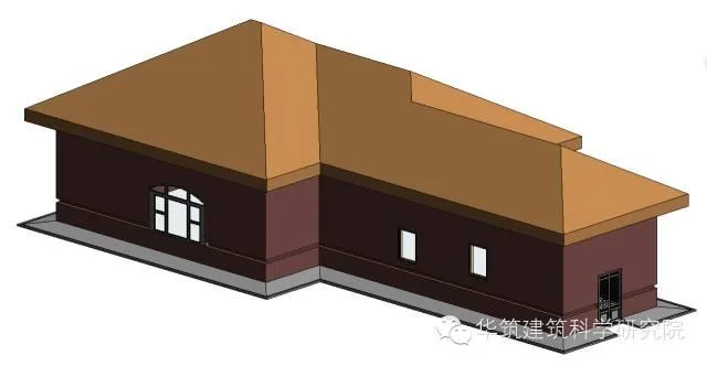
When working on modeling, you might face the challenge of drawing drip edges (scattered water) on buildings. Nowadays, many buildings have drip edges outdoors, but sometimes these details are overlooked when drawing exterior walls. This omission can lead to inaccurate modeling and calculations. If the area affected is large, making corrections later becomes difficult. To help with this, here is a guide on how to add drip edges to walls during the drawing process.
Step 1: Go to the Building tab, select Wall, then click Edit Type to open the Type Properties dialog box for the wall.
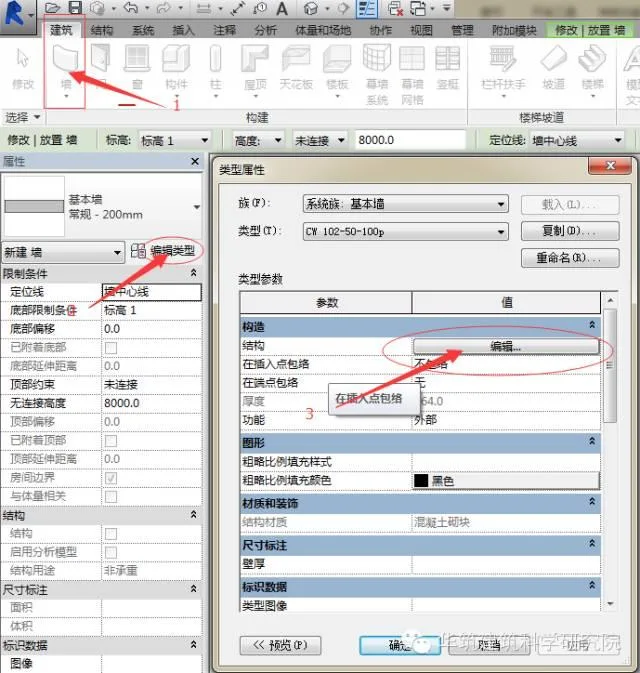
Step 2: Inside the Edit Type window, open the Edit Component dialog box. Then open the preview and switch the view mode to Section.
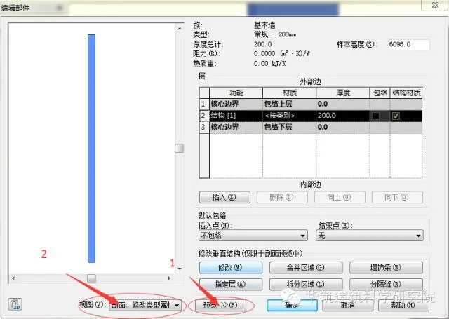
At this stage, the Modify and other related function buttons will become active, as shown below. If the view is not set to section display, these buttons will remain grayed out.
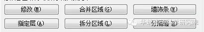
Step 3: Select Wall Decoration Strips, then click Add in the pop-up dialog box for wall decoration strips. The result appears as shown below.
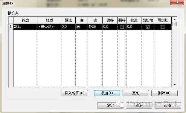
You can choose the desired profile from the contour drop-down menu.
Step 4: If you don’t find a suitable profile, you will need to load one into your project manually. Click on Load Profile to open the Load Family dialog box.
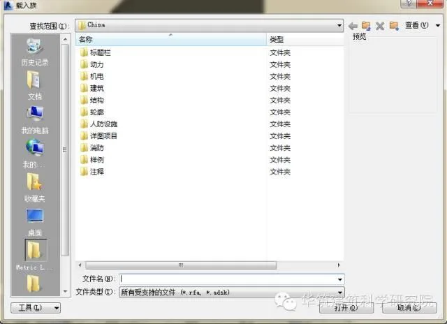
Select the profile you need (in this example, a drip edge profile). Navigate through Outline > General Outline > Venue to find the appropriate file. This will bring up a dialog box as shown below.
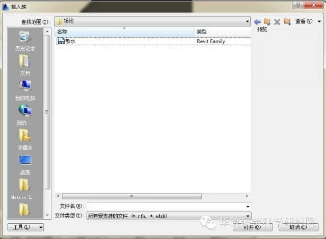
Choose the drip edge file and click Open to load it into the project.
Step 5: Back in the Wall Strips dialog box, click the contour drop-down menu and select the profile you just loaded.
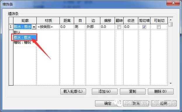
Click OK. From now on, when you draw the wall, the drip edge will be automatically added to it.
The procedure for adding partition joints is similar to the steps for wall decoration strips. Feel free to experiment and practice this method yourself.


Must log in before commenting!
Sign Up