Abstract: The Wanda Wuhan Runway project leverages the robust virtual construction capabilities of BIM technology to enhance collaboration among Wanda and other stakeholders throughout the entire implementation process. This approach minimizes construction risks and elevates the level of project management.
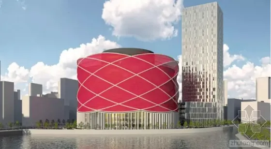
Wuhan Wanda Runway Rendering
The complexity of the Wanda Wuhan Runway significantly surpasses that of typical construction projects, rendering traditional engineering planning, design, and implementation management methods insufficient. To address this, the project team utilized BIM technology to create an information-sharing platform that coordinates the engineering requirements of all involved parties. BIM was not only employed as a tool for pipeline integration and detailed design but was also further applied during the construction phase to provide effective support for overall project management.
This innovative application of BIM technology not only broadens the company’s existing business scope but also demonstrates pioneering and forward-thinking potential for BIM implementation within China.
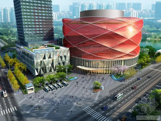
Wuhan Wanda Runway Rendering
The Wanda Hanxiu Theater in Wuhan covers a building area of 86,000 square meters, featuring three underground floors, one above-ground floor, and sections reaching up to eight floors. It accommodates 2,000 seats, including VIP-exclusive passages and seating. The Hanxiu Theater boasts several world-firsts:
- The largest performing arts theater worldwide in terms of investment;
- The first-ever dreamlike stage capable of combining plot dynamics with movement, tilting, and infinite variations;
- The first audience seating system that can move, rotate, and lift;
- The first flying and moving LED giant screen;
- The largest stage performance pool globally, measuring 58 meters long, 32 meters wide, and 10 meters deep;
- The most challenging stage performance, including a 24-meter-high diving act.
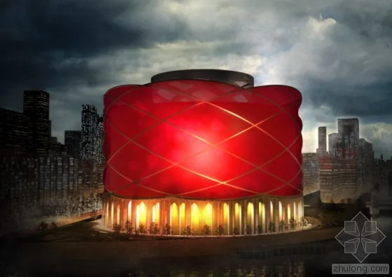
Wuhan Wanda Runway Rendering
This highly complex single building is the first of its kind in China. The specialized theater equipment—such as lifting stages, lifting seats, and rotating seats—requires direct contracting and management by Wanda. Additionally, the project necessitates multi-party coordination between the general contractor and various specialty equipment contractors to ensure seamless workflow integration during implementation.
In this project, the BIM model developed by the Chengdu BIM team provided a visual platform and functioned as a management tool. Experienced on-site engineers deployed BIM management applications tailored to Wanda’s management characteristics. Key services included creating 4D progress models, optimizing technical solutions based on these models, and leveraging BIM technology to assist project management during construction. This digital approach enhanced project control, increased stakeholder engagement, reduced late-stage construction risks, and improved overall project management.
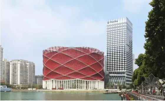
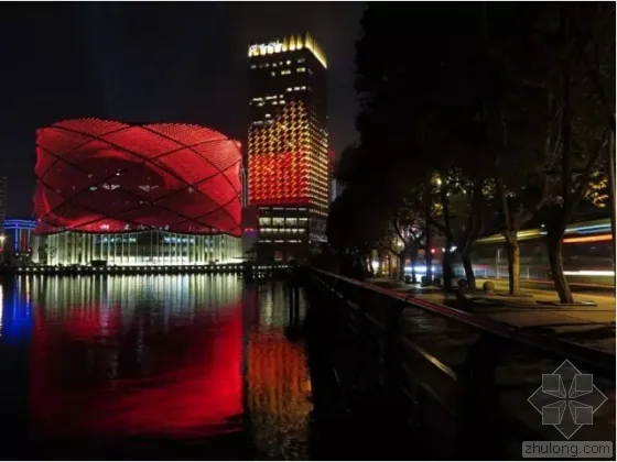
Wuhan Wanda Runway – Daily View
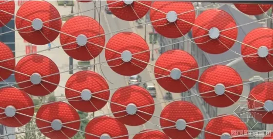
The Wuhan Wanda Show is a world-class stage production jointly created by Wanda Group and Frank Degong Entertainment Group. The runway features innovative and unique expression techniques that cleverly blend rich Chinese cultural elements with modern technology. Its meticulously crafted appearance and well-planned functional layout make it a striking landmark by East Lake and Fruit Lake in Wuhan, symbolizing the traditional Chinese “red lantern.”
The runway was designed by globally renowned designer Mr. Mark Fischer, covering approximately 86,000 square meters. It includes a 2,000-seat auditorium, dry and wet performance stages, front and back service areas, and mechanical equipment zones. The audience seating features rotating and lifting seats. The performance area includes a water performance pool with a lifting platform holding over 10,000 cubic meters of water, a dry stage with a lifting platform, a three-axis motion mechanical arm LED giant screen, a large aerial stunt truss, a double-layer fully suspended grid roof, and four underground equipment layers.
The architectural design and internal space of the runway are highly complex. Structural engineers faced significant challenges in designing and constructing the spacious, multifunctional, and uniquely shaped Red Lantern Theater. Below is an overview of the design and construction of the theater’s main structure.
Main Structure Design and Construction
Architectural Expression and Typical Floor Plan
The entire lantern building stands about 71 meters tall, with a circular floor plan approximately 110 meters in diameter.
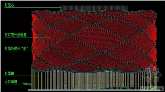
Red Lantern Facade Composition
The exterior facade comprises the lantern shell, circular “ribs” supporting the shell, the lantern spike, and the lantern core. The skin is made up of over 18,000 aluminum alloy discs, each about 800mm in diameter, supported by eight circular ribs that form the structural framework.
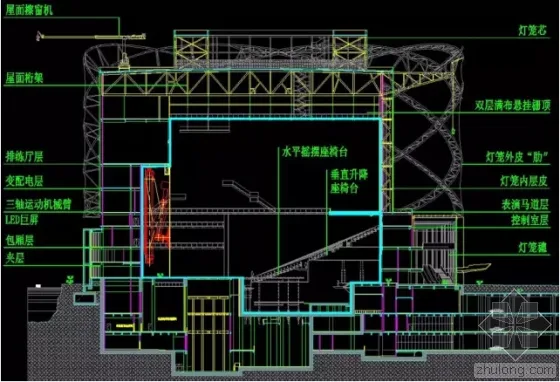
Red Lantern Section Composition
Inside, the Lantern Theater is exceptionally spacious, with functional rooms arranged around each floor and floor slabs. The central area of the above-ground main structure is nearly hollow, spanning roughly 30 meters in height from the second floor to the top fence. Floor plan openings range from a minimum horizontal width of 54 meters and vertical height of 60 meters to a maximum horizontal width of 68 meters and vertical height of 87 meters.
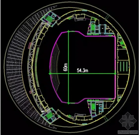
Minimum Floor Plan Opening (Performance Track Level)
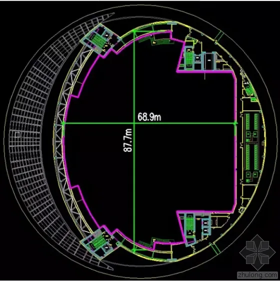
Maximum Floor Plan Opening (Transformer and Distribution Floor)
Main Structural System Selection
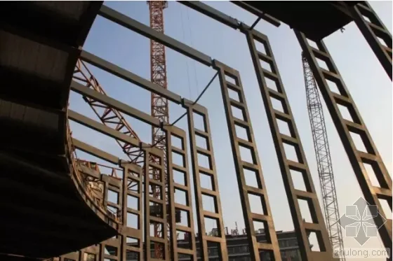
To meet the architectural and performance requirements while maintaining the building’s distinctive shape, the runway employs a steel frame multi-tube structural system with four main tubes for lateral force resistance. These “giant tubes” surround the runway perimeter, supporting the heavily loaded roof and serving as the main lateral force-resisting elements.
To accommodate the theater’s internal needs, the roof requires a large-span capability, with a maximum span of 70 meters. A main truss, standing 6 meters high, is installed between the giant core tubes to achieve this.
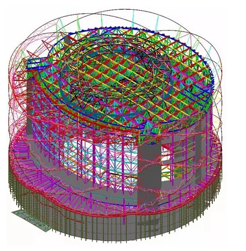
Overall Structural Skeleton Model
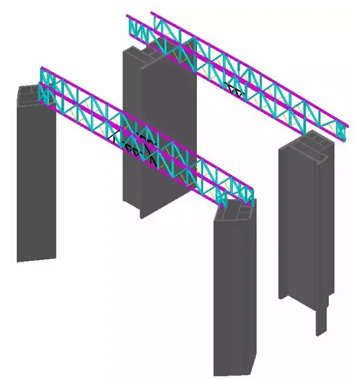
Main Roof Truss Spanning 70m
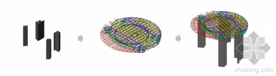
Main Load-Bearing Model Composition
Steel frames are also arranged around the four tubes to support surrounding building functions.
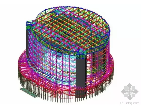
Surrounding Steel Frame Structure Layout
The roof truss supports several components, including the horse track layer, back-area rehearsal hall, aerial stunt truss, fence top layer, pulley beam layer, and the roof sightseeing lantern core.
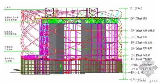
Floor Elevation Schematic Diagram
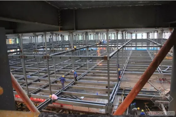
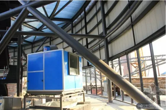
Main Structure Construction
The roof truss, the key component of the main structure, required approximately 3,200 tons of steel. Due to its large span, numerous components, and heavy weight, the typical approach of full hall supports and high-altitude bulk splicing was deemed time-consuming and expensive.
After several discussions, the core roof truss section—including the top layer of the hanging grid and flight track—was assembled using an overall lifting method. This core section measures 81 meters in length, 68 meters in width, covers 4,300 square meters, and weighs about 1,700 tons. The shaded area in the image below illustrates the lifting scope:
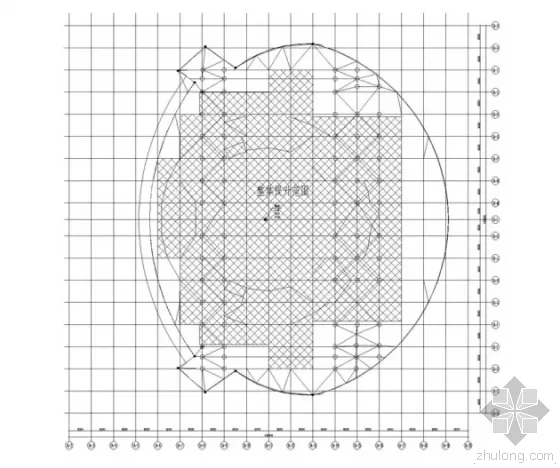
Roof Truss Overall Lifting Area
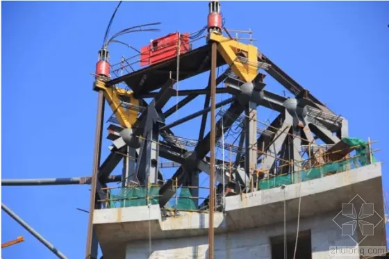
Top Lifting Point of Core Tube
Roof Truss Lifting Process
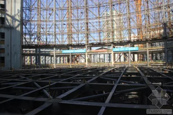
Preparation for Overall Lifting of Suspended Grid Layer at Roof Truss Base
Preparation for Flight Orbit Elevation
This overall lifting scheme significantly shortened the steel structure installation timeline on-site and improved installation quality.
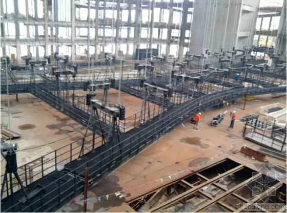
The front wall has an unsupported height of 27 meters and a horizontal length of 80 meters. To address this, a 3-meter-thick cylindrical bidirectional cross truss was installed between the two core tubes at the front, with steel columns on the outer cylindrical surface transitioning at the 19-meter floor elevation.
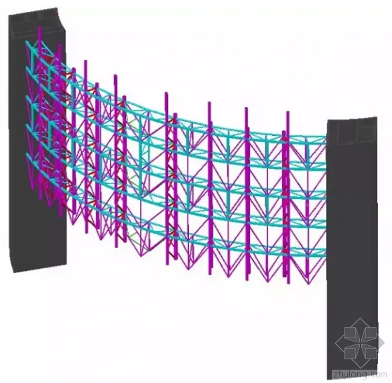
Front Hall Column Double-Sided Cross Truss
Construction of Bidirectional Cross Truss on Front Hall Column Surface
Exterior Structure Design and Construction of the Red Lantern
Architectural Concept
The overall shape of the Red Lantern consists of three main parts: the lantern body, the lantern tassel, and the lantern core.
Lantern Body Structural Design and Construction
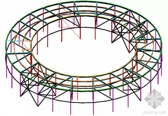
The lantern body is cylindrical, composed of a spoke frame, support system, and outer skin system.
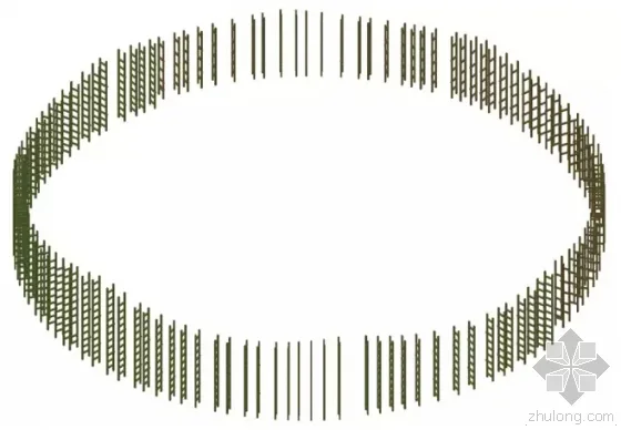
The spoke skeleton features eight intersecting horizontal elliptical rings, each about 110 meters in diameter. These eight ellipses intersect in pairs to form 56 spatial grids, with the longest grid dimension approximately 40 meters. The following figure illustrates the spatial grid formed by the spoke ring tubes:
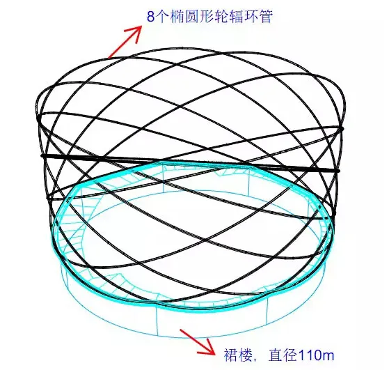
Schematic Diagram of Spoke Skeleton Spatial Grid
Due to the large span of the front hall spokes (over 80 meters straight-line distance), these were designed as spatial cross-truss structures. The rear section uses a single-tube cross-spoke structure made from 400mm diameter steel pipes. The spoke skeleton connects the external curtain wall to the main structure through umbrella-shaped supports, roof overhanging trusses, frame columns, and spoke supports atop the podium.
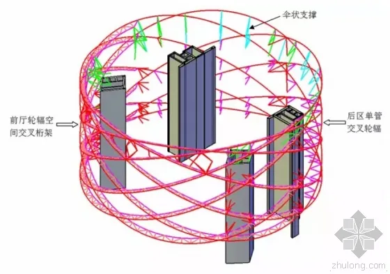
Composition of Spoke Frame and Support System
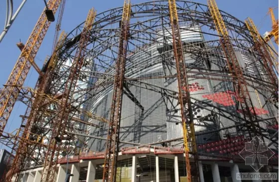
Construction Site of Front Hall Spoke Structure and Lantern Skin Mesh
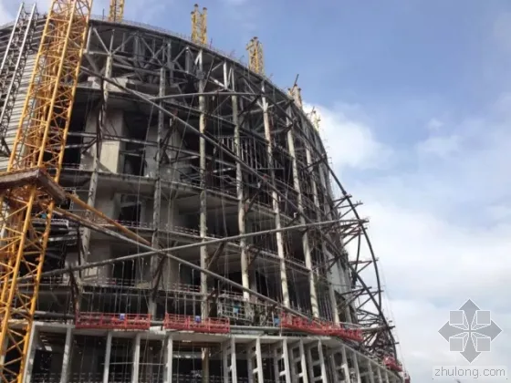
Construction Site of Rear Spoke Structure
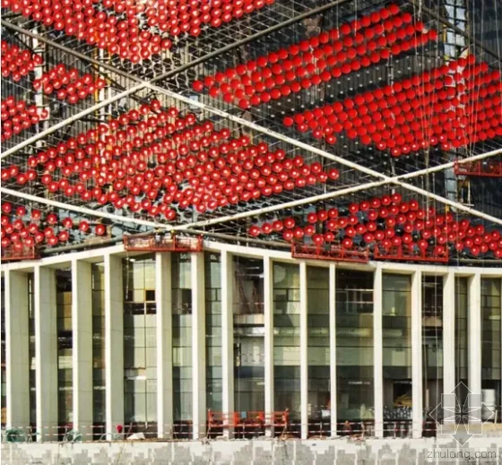
The 56 outer skin panels formed by the intersection of the eight elliptical spoke rings use a single-layer curved cable mesh structure with bidirectional cables on each mesh. When tensioned and pre-tightened, the mesh naturally forms a saddle surface. Circular decorative discs approximately 800mm in diameter are placed at each cable intersection to create the lantern’s distinctive appearance.
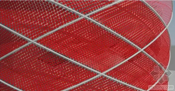
Schematic Diagram of Single-Layer Curved Cable Net Curtain Wall
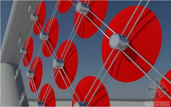
Node and Construction Drawing Rendering
Cable Net and Construction Site
To optimize steel cable usage, a single cross cable was installed behind each disc. In total, 2,135 stainless steel cables with a diameter of 20mm were used for the surface cables, along with more than 18,000 red aluminum alloy discs.
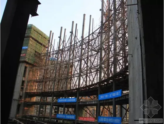
Lantern Tassel Structural Design and Construction
To achieve a slender architectural effect, the lantern tassel features lattice columns measuring 19 meters in height and 0.3 meters in width. These tassels not only fulfill the building’s stylistic requirements but also support various podium floors and provide foundational support for the outer spokes.
Lantern Tassel Grid Structure Column Arrangement
On-Site Construction of Lantern Tassel Lattice Columns
Completion of Lantern Tassel Outer Cladding
Lantern Core Structural Design and Construction
The lantern core serves as a key architectural element, housing roof sightseeing areas, solar energy installations, and concealed rooftop air conditioning equipment. It measures approximately 59.2 meters in outer ring diameter, 38 meters in inner ring diameter, and stands about 11 meters tall. The roof equipment and sightseeing stairs are concealed within the 10-meter ring. The structure employs a supported steel frame design to fulfill functional requirements while minimizing steel usage.
Lantern Core Component Layout
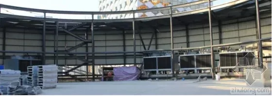
Construction Site Inside the Lantern Core
Construction Site Inside Lantern Core Ring
Wuhan Wanda Show
The Wuhan Wanda Show project commenced design in July 2011 and officially opened in December 2014. The combined design, construction, and program rehearsal phase spanned three and a half years, utilizing approximately 11,000 tons of construction steel to build China’s largest theater with the most complex performance functions. The design team celebrates the successful design, construction, completion, and opening of the Wanda Runway with immense pride and joy.
Project Owner
Wuhan Wanda Donghu Real Estate Co., Ltd.
Main Economic and Technical Indicators
- Total land area: 26,886 square meters
- Total construction area: 162,486 square meters (including 93,132 square meters above ground and 69,354 square meters underground)
- Total building height: 59.8 meters; roof landscape construction height: 71.6 meters
Conceptual Design Team
STUFISH Architects and Production Designers for Entertainment
Design Team for Plan Deepening, Preliminary, and Construction Drawings (LDI)
Project Leader: Huang Jie
Architectural Professional Leaders: Zhang Guiling, Huang Haoshan
Architectural Designers: Zhang Guiling, Huang Haoshan, Zhao Liangxing, Zheng Guanrong, Wei Ke, Xu Yongkun
Structural Design Manager: Huang Taiyun, Fu Jingming
Structural Design Designers: Du Yuanzeng, Bian Jianfeng, Zhu Dongfeng, Li Yuanbo, Li Weiyong, Zhuang Xin
Water Supply and Drainage Designers: Ye Jun, Zhu Xiaoli, Ni Yi, Zhang Haixuan
Electrical Major Responsible and Designers: Chen Guangquan, Tan Binglian, Qiu Xingyu, Cen Yongliang, Li Jiansong
HVAC Professionals Responsible and Designers: Luo Zhiyan, Zhang Shen
Project Manager: Wu Huihong
Performance Craft Design Team
TPC Theater Projects Consultants
Original Drawing Unit
Guangzhou Pearl River Foreign Funded Architectural Design Institute Co., Ltd.
LDI Design Team (Current Unit)
Beijing Architectural Design and Research Institute Co., Ltd. South China Design Center
Special Author of this Manuscript
Du Yuanzeng


Must log in before commenting!
Sign Up