1. Project Overview and BIM Usage Background
The Brigrig River Valley Cable-Stayed Bridge is situated on the Rabat Ring Expressway in Morocco, approximately 30 km east of Rabat, the capital city. The main bridge features a composite beam cable-stayed design with spans measuring 183 m, 376 m, and 183 m respectively (see Figure 1). It crosses the Brigrig River Valley, with a dam storage area located 1 km upstream from the bridge site. The project owner is the Moroccan State-owned Highways Company (ADM), which launched an international open tender in early 2010. The China Overseas Bridge Bureau consortium won the bid and was responsible for both construction and detailed design. The Daqiao Institute (Wuhan, China) and EGIS (France) design consortium acted as the general contractor’s design subcontractor, handling the construction drawing design work.
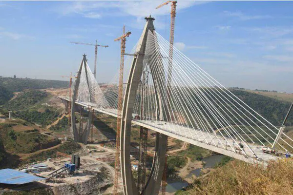
Figure 1: Brigrig Cable-Stayed Bridge in Morocco
Morocco has a long-standing historical connection with France. In bridge engineering, Moroccan projects strictly follow French engineering practices, including design, review, construction, and supervision, all adhering to French norms and standards. The project owner’s expectations for the aesthetic quality and construction refinement are notably higher than typical Chinese standards, which demands greater precision in design. Traditional two-dimensional design methods would struggle to fulfill the needs of both the construction team and the owner. However, the adoption of BIM technology effectively addressed challenges faced by conventional 2D design. The design outcomes from the Daqiao Institute and EGIS consortium met the requirements of all stakeholders, ensuring smooth project progress.
Application of BIM Technology in Structural Design
2.1 Bridge Tower Design
The preliminary design was led by French architects, who envisioned a hyperbolic concrete bridge tower with a shuttle-shaped facade, creating a tall and majestic presence in the valley. The tower consists of four limbs, separated longitudinally and transversely. Each limb column connects to the lower tower column through a concrete skirt plate. A prestressed concrete crossbeam located midway up the tower column provides structural stability by tying the tower column to the bridge deck (see Figure 2). The cross-section of the bridge tower continuously changes from the base to the top (see Figure 3).
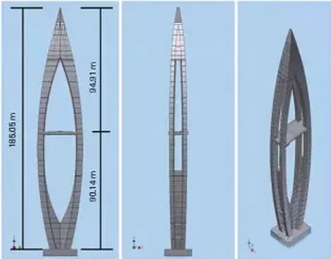
Figure 2: BIM Model of P2 Bridge Tower
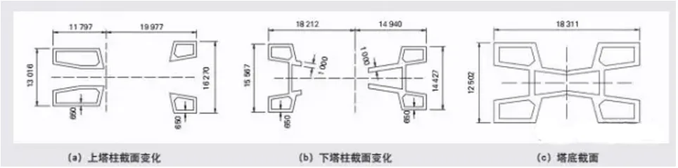
Figure 3: Bridge Tower Cross-Section
The bridge tower’s four-limb spatial curved shape is complex, making it difficult to accurately represent and dimension using traditional 2D design methods. To overcome this, China Railway Major Bridge Institute and EGIS chose to adopt BIM technology for the tower design. They utilized Autodesk Inventor Professional, a BIM software with which EGIS has been experienced for over a year, benefiting from its superior interoperability with AutoCAD. Given the software’s high demands on graphics cards and memory, China Railway Bridge Institute provided a professional graphics workstation for the Moroccan project team to ensure smooth operation.
At the project’s outset, both EGIS and China Railway Major Bridge Institute dedicated significant resources to creating a detailed 3D model of the terrain and landforms surrounding the bridge site. This model was not only used for 2D mapping but also directly applied to the design of concrete formwork. This approach replaced the traditional workflow of “3D in mind → 2D drawings → 3D in construction” with a streamlined process of “3D in mind → digital 3D model → 3D in construction.” The concrete formwork manufacturer, Doka Austria, produced formwork directly from the 3D model of the bridge tower, ensuring precise formwork fabrication and preserving the elegant linear aesthetics of the tower.
2.2 BIM Model and 2D Drawings
While the project achieved direct “digital 3D to construction 3D” conversion for concrete formwork production, 2D drawings remain part of the design process, primarily for review and verification purposes without direct construction impact. Most 2D structural drawings were generated using the engineering drawing module within Inventor software, creating a link between the 2D drawings and the 3D model. Designers only need to update parameters in the design tables, and the 2D drawings automatically reflect those changes. Additionally, shadow rendering was applied to improve the clarity and legibility of the 2D drawings (see Figure 4).
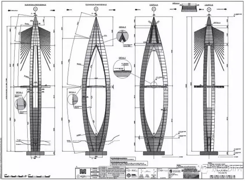
Figure 4: Two-Dimensional Engineering Drawing of the Bridge Tower
2.3 Precise Concrete Quantity Calculation
The complex shape and spatial curvature of the bridge tower make concrete quantity estimation challenging with traditional 2D methods. BIM technology simplifies this task by enabling accurate quantity take-offs through the Bill of Materials (BOM) function. This allows detailed analysis of concrete volume for each section and the entire tower (see Figure 5).
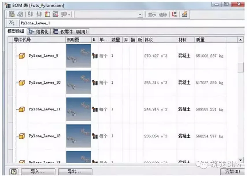
Figure 5: Bill of Materials Quantity Calculation
2.4 Design of Anchor Blocks and Anchor Slots for Main Beam Diagonal Cables
The main beam’s inclined cables use groove anchoring, with anchor blocks located at the cable conduits (see Figure 6). Since the angles between the inclined cables and the horizontal plane vary in both longitudinal and transverse directions, each anchor groove and block differs in size. Traditional 2D design requires complex geometric calculations to determine these sizes. BIM technology allows parametric 3D modeling to easily generate accurate dimensions for all anchor grooves and blocks.
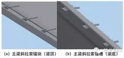
Figure 6: Main Beam Cable
2.5 Accurate Excavation and Filling Calculations
The bridge tower foundation utilizes open excavation, generating significant earthwork during construction. Traditional 2D design makes accurate calculation of excavation and filling volumes tedious. BIM technology, however, provides precise estimates of on-site earth and rock quantities. Figure 7 shows the open cut foundation of the bridge tower.
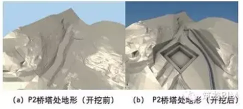
Figure 7: Open Cut Foundation of Bridge Tower
Application of BIM Technology in Reinforcement Engineering Design
3.1 Lightweight Components with High Reinforcement Ratios
The design, led by architects, aimed to achieve an aesthetic impact with lightweight components despite the tower’s considerable height of nearly 200 m (P1 at 197.45 m; P2 at 185.05 m). Most tower limbs have wall thicknesses as thin as 65 cm. This resulted in a high reinforcement ratio, with numerous high-strength steel bars (500 MPa yield strength, 40 mm diameter) used. Reinforcement ratios for most limbs hover around 300 kg/m³, with the L5 section reaching 400.49 kg/m³. Prestressed ducts run transversely through the tower, increasing the risk of collisions between steel bars and between steel bars and prestressed pipes.
3.2 Detailed Design and Factory Prefabrication of Reinforcement
Reinforcement processing follows the owner’s requirements and French engineering practices, emphasizing large-diameter steel bars. All steel bars are prefabricated in the factory (see Figure 8) and assembled onsite. Cutting and bending steel bars onsite is prohibited; connections rely on binding and overlapping. These constraints demand thorough consideration during the design phase, shifting the design center forward and significantly increasing the workload of the design institute.
During reinforcement design, China Railway Major Bridge Institute considers factors such as construction segment length (4 m per tower segment), maximum steel bar length (factory length ≤ 12 m), overlap length and interlocking ratios that comply with specifications, hoop reinforcement configurations, installation sequence, worker space requirements, and smooth concrete pouring. (Note: In Chinese engineering, these aspects typically fall under construction organization, primarily the contractor’s responsibility.)
3.3 Using BIM for 3D Collision Detection of Steel Bars
China Railway Major Bridge Institute uses Inventor software to create precise structural drawings of reinforcement, which are then imported into AutoCAD for 2D reinforcement detailing. Realistic dimensions for length, diameter, bending radius, hook shape, and hook length are applied to avoid reinforcement collisions. While 2D design satisfies most owner requirements, complex areas require 3D tools. The institute developed an independent plugin to generate 3D steel reinforcement cages from 2D drawings, enabling collision detection and adjustment of steel bar positions to improve construction efficiency (see Figure 9).
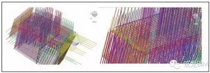
Figure 8: Three-Dimensional Steel Cage of a Bridge Tower Section
Application of BIM Technology in Steel Anchor Box Design
As the primary load-bearing element of cable-stayed bridges, accurate positioning of anchor points is critical to the overall structural performance. To enhance positioning accuracy, the anchorage scheme for the tower was changed from an initial circumferential prestressing design to a steel anchor box scheme. Each tower supports 20 pairs of stay cables anchored within an approximately 24 m high zone at the tower top, resulting in very tight cable spacing. The minimum center-to-center spacing between cables is 935 mm; after subtracting the cable conduit diameter, the net spacing narrows to just 390 mm. This limited space poses challenges for welding during steel structure fabrication.
To ensure precision in steel structure fabrication, the design team developed a 3D BIM model of the steel anchor box (see Figure 10), which is directly used to generate detailed drawings. Combining 2D and 3D views in these engineering drawings helps the steel fabricator plan the installation and welding sequence more efficiently, boosting manufacturing productivity.
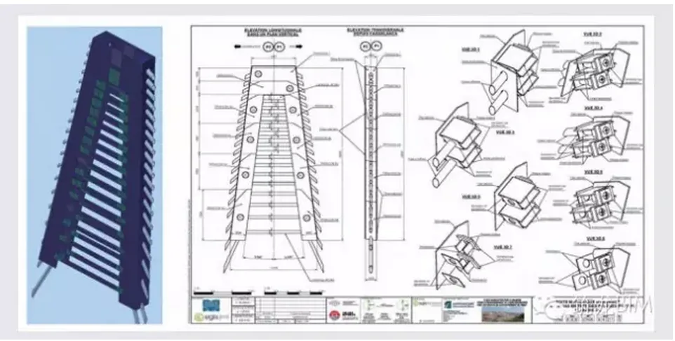
Figure 9: BIM Model and 2D Engineering Drawing of Steel Anchor Box
5. Conclusion and Outlook
(1) The Brigrig River Valley Cable-Stayed Bridge project marks the first time China Railway Major Bridge Institute designed a bridge fully compliant with French codes, standards, and construction practices. BIM technology played a vital role in meeting owner and contractor requirements, facilitating smooth project progression, and establishing a solid foundation for BIM adoption in bridge engineering by the institute.
(2) Throughout the design process, the China Railway Major Bridge Engineering Group partnered with French EGIS to apply BIM for complex modeling, 2D drawing, quantity take-offs, and collision detection, effectively resolving design and construction challenges. This collaboration accelerated BIM proficiency at the Daqiao Institute, saving time on learning and exploration.
(3) BIM technology encompasses extensive system engineering. This project primarily focused on the Modeling (M) aspect, with less emphasis on the Information (I) component. Future BIM applications should increasingly leverage robust information management and communication.
(4) BIM can deepen bridge design and better guide construction. Promoting prefabrication and industrialization through digital bridge technologies can enhance construction precision and project quality. Conversely, construction and manufacturing digitalization can also accelerate BIM adoption.
(5) BIM adoption should be progressively encouraged to shift designers’ mindset towards initiating projects with 3D design at the conceptual stage, embedding BIM thinking throughout the entire design process.
References
Liao Mujie, Liu Xiaolin. Design and Technical Characteristics of the Brigrig Composite Cable-Stayed Bridge in Morocco. World Bridges, 2012, 40 (4).
Author: Liu Jie, Engineer, China Railway Bridge Survey and Design Institute Group Co., Ltd.
Professor-level Senior Engineer Ma Runping, China Railway Bridge Survey and Design Institute Group Co., Ltd.
Xu Rundong, Senior Engineer, China Railway Bridge Survey and Design Institute Group Co., Ltd.


Must log in before commenting!
Sign Up