In 2015, the term “Internet” was officially incorporated into Premier Li Keqiang’s government work report, marking its inclusion in the nation’s top-level strategic design and highlighting its significance for economic and social development. This era has seen dramatic transformations across many traditional industries. As a technology-intensive field, the construction industry must adapt to these changes by seeking new breakthroughs and development opportunities. At the heart of Building Information Modeling (BIM) is the creation and transmission of information within the construction sector. This information serves as the data foundation for integrating construction into the “Internet” era and acts as a driving force propelling the industry forward.
This article uses the China Enterprise Pavilion at the 2015 Milan World Expo as a case study to comprehensively review the application of BIM technology. It shares the project’s design concepts and challenges, highlights the key features of BIM implementation, and concludes with a discussion of existing issues in BIM technology within architectural design.
Project Design Concept
The 2015 Milan World Expo in Italy centered on the theme: “Feeding the Planet, Energy for Life; Joining Hands for Food Safety, Food Security, and Healthy Living.” Reflecting this theme, the China Enterprise Pavilion adopted “Chinese Seeds” as its symbolic image to represent the growth and development of Chinese enterprises (Figures 1 and 2).
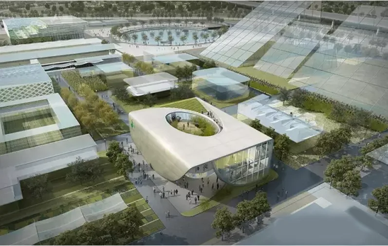
Figure 1: China Enterprise Joint Pavilion
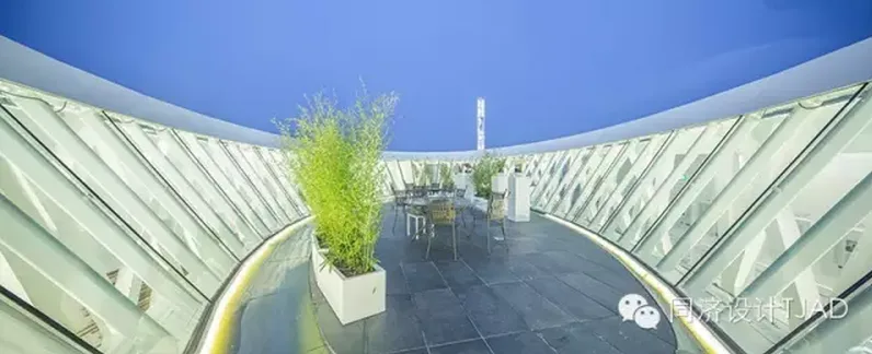
Figure 2: China Enterprise Joint Pavilion Zhongyi Garden
The architectural inspiration draws from the concept of “seeds,” embodying themes of nature and life in multiple ways. The dynamic skin of the building simulates seed germination and growth, while the double circular ramp symbolizes a DNA molecule structure. Vertical greening at the building’s core breathes vitality into the interior. Furthermore, the design explores dualities such as “square and circle,” “inside and outside,” “virtual and real,” “rigid and flexible,” and “movement and stillness,” reflecting philosophies of harmony with nature and coexistence of presence and absence. From any vantage point, the seamless connection between interior and exterior spaces is evident, allowing air and light to penetrate deeply into the building.
Design Challenges
Nonlinear Design
To capture the ethos of “Dao follows nature” and “existence and non-existence coexist,” the design incorporates numerous nonlinear elements, from the exterior contours to the circular atrium. The building’s form is a square volume embedded with tree-shaped columns, a circular atrium, and a green core. The design eschews traditional orthogonal lines in favor of dynamic curved surfaces to ensure a smooth transition of visitor flow between inside and outside. Visitors can reach the rooftop garden seamlessly without awareness of the transition (Figures 3-5).
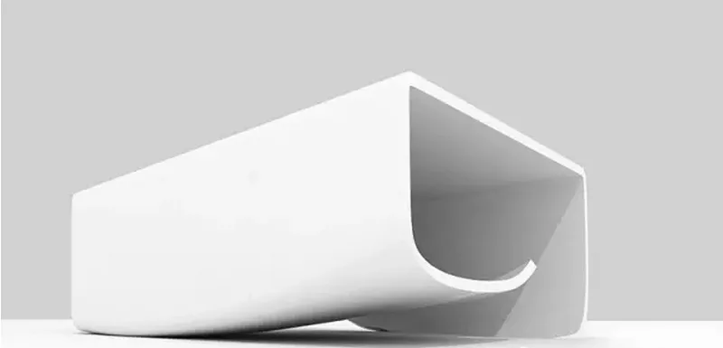
Figure 3: Building Exterior Surface
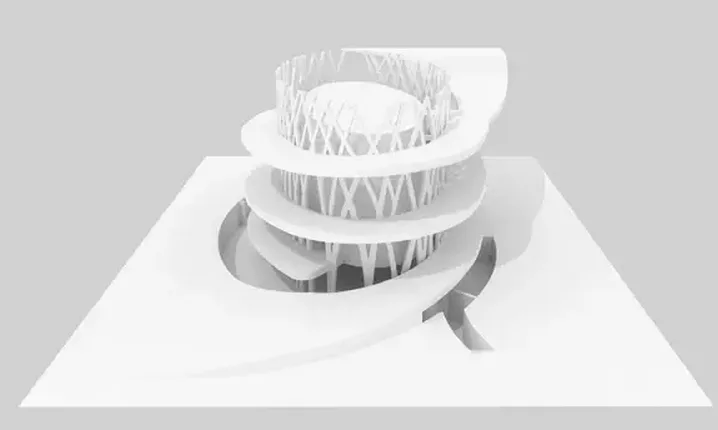
Figure 4: Circular Rotating Ramp
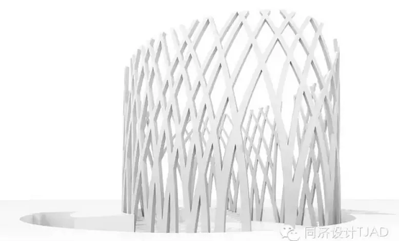
Figure 5: Tree-like Column
Limited Building Space
The Milan World Expo allocated relatively small land plots for each exhibition hall, with tight surrounding road spaces. Height restrictions limit all exhibition halls outside the National Pavilion to 12 meters, while indoor spaces must maintain a minimum net height of 3 meters for comfort. The China Enterprise Pavilion, jointly funded by multiple companies, required approximately 2,000 square meters of usable area within a 930 square meter site—a significant challenge for building, structural, and equipment engineers to maximize space while meeting clearance requirements (Figures 6 and 7).
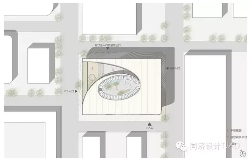
Figure 6: General Plan
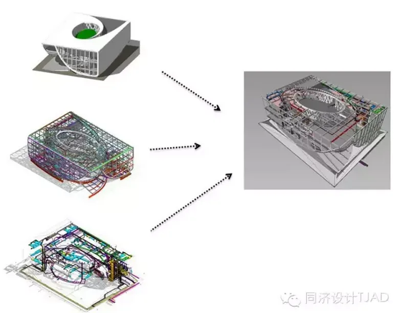
Figure 7: BIM Design Model
BIM Design Process
To address these challenges, the design team adopted BIM technology early on, utilizing 3D models for design. Various disciplines collaborated closely, providing timely feedback to resolve issues and deliver a high-quality design efficiently (Figures 8 and 9).
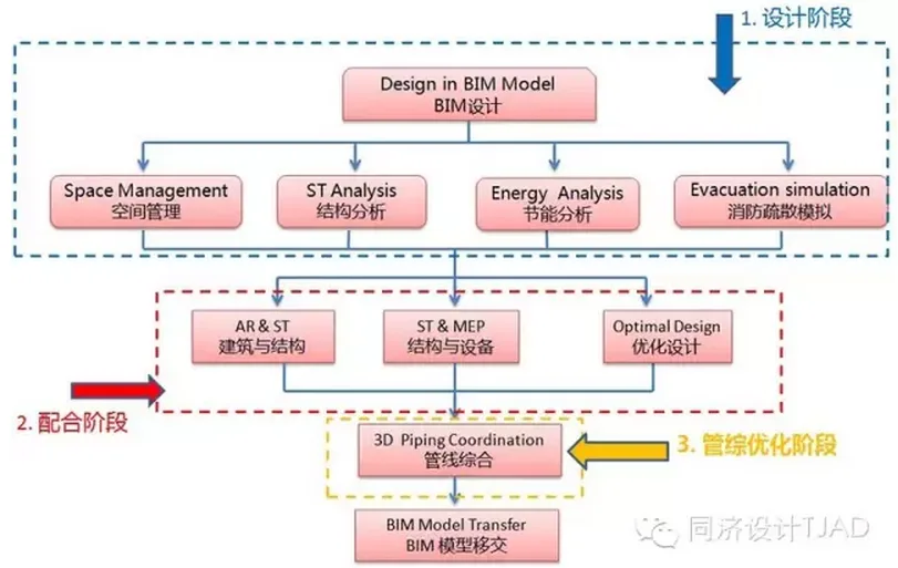
Figure 8: BIM Design Process
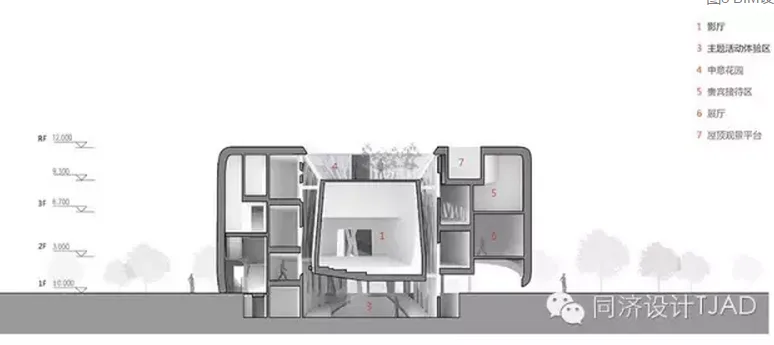
Figure 9: Sectional View
During the early design phase, civil engineers collaborated within the BIM model to establish the building’s overall form, boundaries, and structural system. They identified and resolved potential bottlenecks across disciplines to avoid disruptive late-stage changes. Once confirmed, each specialty deepened its model to prepare for further interdisciplinary coordination.
In the mid-stage, architectural and structural BIM models were refined to construction drawing detail. Architects ensured building functions and spaces aligned with structural layouts. Equipment engineers incorporated major pipelines and large equipment into the model. When clashes were detected, the equipment and structural teams coordinated to find optimal solutions and prioritized follow-up tasks.
In the final optimization phase, architecture and structure teams continuously updated the model, making local adjustments as needed. Equipment teams fully integrated all branch piping and equipment into the BIM model. Structural engineers created reserved openings in the BIM model based on actual pipeline dimensions, guiding subsequent detailed design and construction installation effectively.
BIM Design Highlights
Facade Truss
Given the building’s compact size, the design strategy emphasized simplicity and strength through pure materials and minimal detailing. At the entrance, the exterior skin lifts to form a large arc tangent to the ground, extending to the roof (Figures 10 and 11). The structural engineer developed a facade truss adapting to the building’s outline, efficiently transferring and distributing forces, creating a “curtain lifting” effect. Large overhangs eliminate columns at the entrance, blurring the boundary between interior and exterior and creating an open, inviting space (Figure 12).
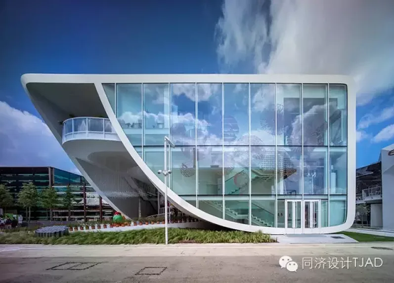
Figure 10: Entrance Large Cantilever Structure
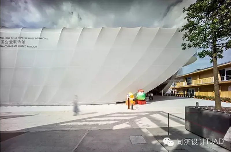
Figure 11: Outer Skin Design
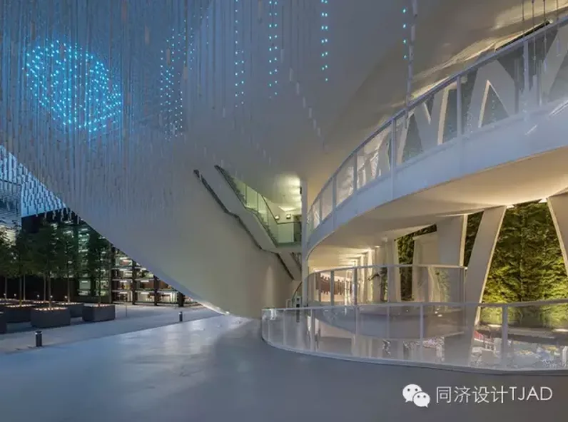
Figure 12: Intermediary Space Inside and Outside the Building
Designers leveraged BIM tools, initially modeling the building form in Rhinoceros. Structural designers then used Revit to arrange the structure within this outline and imported the model into structural analysis software. This approach reversed the traditional workflow of 2D positioning guiding 3D modeling, instead using BIM’s 3D visualization to transform abstract concepts into clear spatial relationships. Collaborative BIM workflows allowed immediate design updates and feedback between architecture and structure teams, significantly improving efficiency and quality (Figure 13).
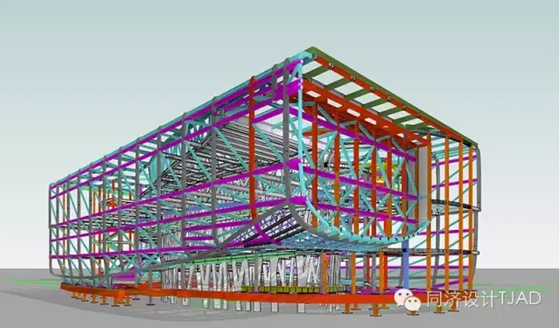
Figure 13: BIM Model of Facade Truss
Tree-Like Column Design
To imbue the structural components with aesthetic meaning, tree-shaped columns were placed at the building core. These interlocking columns form an elliptical column tube, supporting both the structure and architectural expression. The Green Core Cinema is suspended by these columns, with lower supports removable to extend the exhibition hall boundary seamlessly into the column branches. A circular light well enhances the exhibition space. The tree columns also support the circular ramp and are vital structural elements. The columns’ fabrication involved dividing the barrel into two unfolded inner and outer surfaces plus multiple smaller panels, ensuring smooth assembly and surface quality.
Conventional design methods could not accommodate the complex positioning of these interlocked columns, making BIM essential. Architects and structural engineers worked simultaneously within a shared Revit central file. Architects defined column placement and forms, while engineers analyzed structural feasibility, preserving the architectural vision and ensuring structural integrity. Equipment engineers planned piping entirely within the BIM model, avoiding extensive late-stage modifications (Figures 14 and 15).
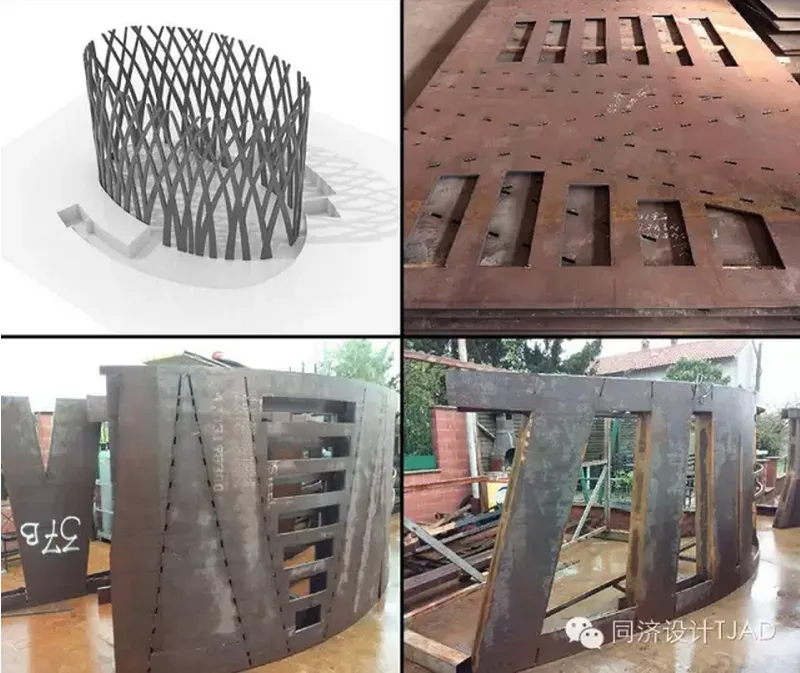
Figure 14: BIM Model of Tree Column and On-site Construction
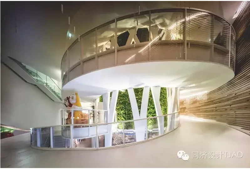
Figure 15: Internal Core Vertical Greening
Comprehensive Pipeline Coordination
With a total building height restricted to 12 meters and indoor spaces requiring at least 3 meters of net height, ventilation and lighting demands were especially high. Optimizing pipeline layout within these constraints was a major design focus. Structural and equipment engineers collaborated to drill holes directly into steel beams, maximizing equipment layout flexibility and streamlining coordination. All disciplines worked simultaneously to schedule pipelines, after which structural engineers reanalyzed and made local adjustments where stress was insufficient. The finalized BIM model included steel beam openings and comprehensive pipeline diagrams, which were shared with the construction team for accurate cutting and installation (Figure 16).
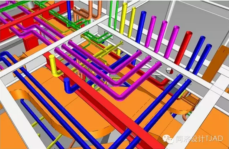
Figure 16: Partial BIM Management Model of China Enterprise Pavilion
Conclusion
The development of BIM technology may face challenges, requiring full support and collaboration from all construction industry stakeholders. However, BIM’s progress is unstoppable. Owners, design firms, construction companies, software developers, and others are all transitioning from traditional approaches to BIM-centric thinking. Only through collective effort can the construction industry realize the profound transformation BIM promises. Together, we embrace this change with optimism, confident that it will ultimately lead to rewarding outcomes.
Authors: Li Li, National First Class Registered Constructor; Zhang Zheng, National First Class Registered Structural Engineer; Wu Jie, National First Class Registered Architect and Senior Engineer


Must log in before commenting!
Sign Up