Introduction
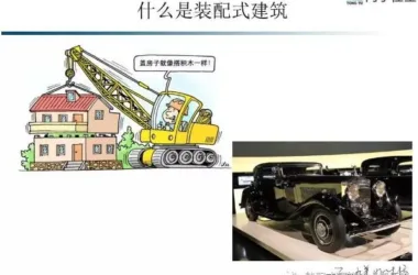
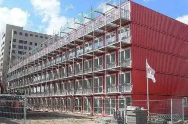
In recent years, with strong support from national and industry regulators, prefabricated and assembled buildings have rapidly advanced. Prefabricated modular buildings allow for early design and planning to integrate secondary structures, insulation, doors and windows, and exterior wall finishes into prefabricated components. This approach significantly reduces on-site construction time and secondary operations, while addressing many quality issues common in cast-in-place buildings.
However, due to rapid industry growth, a shortage of skilled labor, and immature industrial support facilities, three common quality issues persist in the production of precast concrete (PC) components that require careful attention:
1. Structural quality issues: These affect structural safety and are considered critical defects.
2. Dimensional deviations: These may not compromise structural integrity but can affect building functionality and construction efficiency.
3. Appearance quality issues: Usually minor and not affecting structure or functionality, but in projects with high aesthetic demands (e.g., fair-faced concrete), these become major concerns. Additionally, appearance issues often hint at underlying component quality problems.
1. Common Structural Quality Issues
1.1 Insufficient Concrete Strength
Problem Description
PC components may leave the curing pool with insufficient strength, lack adequate transportation or installation strength, leading to inadequate final structural strength. Traditionally, prefabricated components are steam-cured within templates and only released after exceeding 100% design strength, meeting transport, installation, and usage requirements. Currently, many factories produce PC components with low initial strength and inadequate curing, resulting in damage to edges and corners during transport and installation, or even internal defects. Safety concerns arise because anchoring and embedded parts rely on concrete design standards. Insufficient concrete strength can reduce anchoring force, creating hazards.
Root Cause Analysis
The primary causes are short curing times, inadequate curing measures, and lack of concrete strength monitoring. Fundamentally, technical management personnel may be unfamiliar with, underestimate, or insufficiently enforce concrete quality controls.
Preventive Measures
Establish a concrete strength growth curve based on the mix design for quality control. Technical plans should define reasonable concrete release, factory, and installation strength requirements. Daily production should include multiple curing specimens tested periodically. Maintain concrete strength at each stage post-pool release. PC components with strength below design values require special technical controls to ensure safety and quality.
Treatment
If insufficient concrete strength is detected during construction, strengthen curing and test strength via test blocks or rebound methods before proceeding. Components failing to meet design strength must be reviewed with design and supervision engineers for possible acceptance at reduced standards. Components that do not meet structural requirements must be scrapped and replaced.
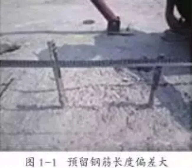
1.2 Excessive Deviation of Steel Bars or Embedded Parts
Problem Description
Excessive positional deviations of steel bars or embedded parts (e.g., grouting sleeves, embedded irons, connecting bolts) can affect appearance and installation, potentially compromising structural stress performance (see Figure 1-1).
Root Cause Analysis
Lack of collision checks during detailed design; poor-quality semi-finished steel bars; absence of anti-deformation supports during lifting and storage; insecure fixing of steel bars and embedded parts; deformation during concrete pouring; no secondary correction before concrete sets; insufficient inspection and technical communication.
Preventive Measures
Use BIM technology during deepening design to perform collision checks between steel bars and embedded parts. Employ high-precision machinery for semi-finished steel bar processing. Account for positional relationships between reserved and cast-in-place steel bars during installation. Ensure firm binding or welding and reliable fixing of steel bars and embedded parts. Assign workers to reset embedded parts and steel bars after concrete pouring. Enforce strict inspection procedures.
Treatment
Rectify deviations promptly during construction. Components failing to meet standards must not proceed to the next stage. Attempt to reset misaligned steel bars and embedded parts; if unsuccessful, measure deviations and consult design and supervision for possible acceptance at reduced standards. Components failing structural requirements must be scrapped and reconstructed.
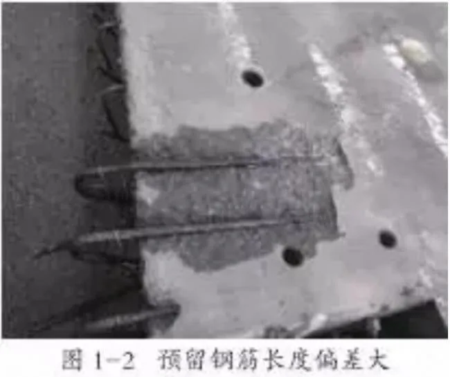
1.3 Inadequate Thickness of Steel Reinforcement Protective Layer
Problem Description
Significant deviations in the protective layer thickness of reinforcement (too thin or too thick) may not be visible but can be detected instrumentally. Such defects impact durability and structural performance (see Figure 1-2).
Root Cause Analysis
Steel reinforcement may be compliant, but component size exceeds tolerance; poor-quality steel bars or skeletons; templates not meeting size requirements; improperly sized or soft protective layer pads; steel skeleton stepping during pouring; inadequate technical communication; insufficient quality inspection.
Preventive Measures
Simulate protective layer thickness using BIM for better control. Use compliant protective pads. Protect semi-finished and finished steel bars. Prohibit stepping or prying on steel bars during pouring. Provide sufficient anti-collapse supports between double-layered steel bars. Strengthen quality inspections.
Treatment
If thickness deviation results from steel reinforcement displacement, consult design and supervision before use, ensuring special protection measures. If due to component dimensional deviations, conduct detailed analysis to determine usability. Despite seeming minor, these issues can be challenging to address and often occur systematically, warranting serious attention.
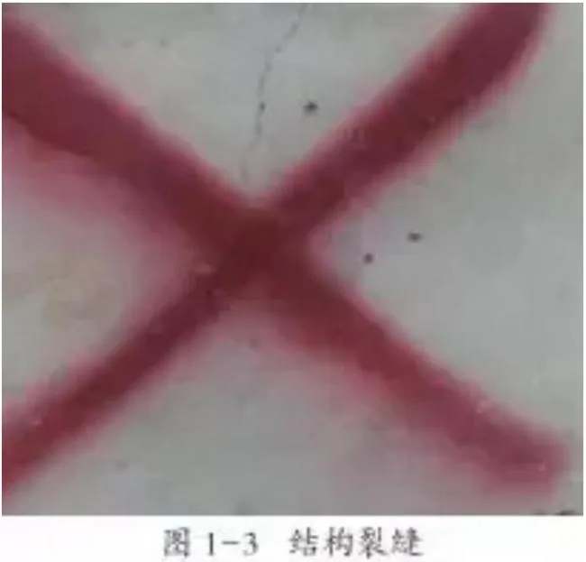
1.4 Cracks
Problem Description
Cracks penetrate from concrete surfaces inward and are classified as surface, deep, or through cracks based on depth. Through or deep cracks (see Figure 1-3) adversely affect component strength, durability, and waterproofing, especially compromising steel reinforcement protection.
Root Cause Analysis
Cracks arise primarily because concrete tensile strength is insufficient to resist tensile stresses, which may result from drying, chemical, or cooling shrinkage, local tension, and other factors. Causes include surface dehydration during curing, rapid temperature changes, improper lifting or support positions, and improper construction measures causing excessive local stress. Concrete strength increases over hydration; if insufficient to counter tensile stress, cracks form and may propagate if stress persists. Compressive stress cracks are rare and typically signal overall failure.
Preventive Measures
Design components with reasonable structural reinforcement, especially for construction loads. Optimize concrete mix to control shrinkage. Implement maintenance during critical strength growth phases. Develop and strictly follow detailed lifting, stacking, transport, and installation plans. Apply curing and protective agents timely for plain concrete components.
Treatment
First, analyze crack causes. For stress-induced cracks, remove or control stress within acceptable limits. For transient stress cracks, treat formed cracks accordingly. Surface cracks under 0.2mm width, 30mm length, and 10mm depth typically do not affect structure; seal to prevent moisture ingress and steel corrosion. Wider, deeper, or continuous cracks require epoxy resin injection and surface sealing. Cracks beyond specifications require special technical plans approved by design and supervision. Severely damaged components should not be repaired.
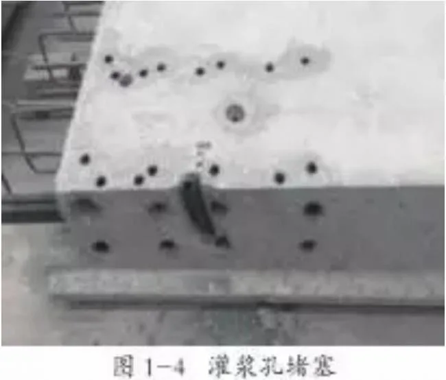
1.5 Grouting Hole Blockage
Problem Description
When using grouting sleeves for steel bar connections, grouting holes or pipes may become blocked, severely compromising grouting quality.
Root Cause Analysis
Oversized rubber plugs sealing the sleeve ends; damaged or bent grouting pipes during concrete pouring; relocation of pipe positioning fixtures; cement slurry leakage into sleeves; excessive grouting material during wall panel installation; inadequate pipe protection allowing foreign object intrusion.
Preventive Measures
Optimize sleeve design for construction quality assurance. Ensure secure fixation and protection of grouting pipes and fixtures. Avoid contact with pipes and positioning fixtures during pouring. Implement rigorous inspection systems to check pipe smoothness during installation, pouring, and final acceptance.
Treatment
Remove surrounding concrete to restore grouting conditions in blocked pipes. After sleeve grouting, repair edges and corners as needed. For components that cannot guarantee grouting quality after chiseling, develop reinforcement plans for design and supervision approval.
2. Common Dimensional Deviation Issues
2.1 Component Size Deviation and Flatness
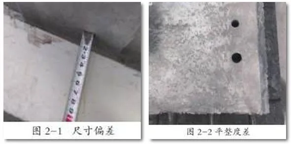
Problem Description
PC component external dimensions, surface flatness, and axis positions exceed allowable tolerances (see Figures 2-1 and 2-2).
Cause Analysis
Inaccurate template positioning or failure to follow drawings; insufficient template strength or rigidity causing displacement during pouring; template deformation from overuse; large component volume and high concrete fluidity causing mold movement; improper stacking and transport leading to plastic deformation.
Preventive Measures
Optimize template design for rigidity and stability. Thoroughly review design drawings and verify first products meet specifications. Ensure template support mechanisms have sufficient load capacity and stiffness. Control vibration to prevent form deformation. Limit concrete slump. Detect and promptly address any mold looseness or deformation during pouring. Implement quality secondary plastering and finishing. Develop and enforce strict stacking and transport procedures. Follow the “three inspections” system rigorously.
Handling
Dimensional deviations affecting structural performance or function are unacceptable. For parts exceeding allowable deviations, treatments like grinding or cutting may be applied. Severe deviations require technical treatment plans approved by design and supervision before processing and reinspection.
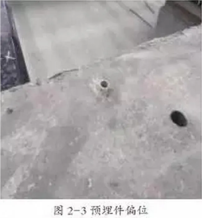
2.2 Dimensional Deviation of Embedded Parts
Problem Description
Center point displacement and axis misalignment of embedded components such as wire boxes, pipelines, suspension points, and reserved holes exceed allowable tolerances, affecting appearance and subsequent decoration (see Figure 2-3).
Cause Analysis
Inadequate design detail causing size conflicts; unreliable positioning prone to displacement; careless construction and insufficient fixing; vibrating rod collisions during pouring; no corrective measures during plastering.
Preventive Measures
Use BIM models for embedded part layout and collision detection in detailed design. Secure embedded parts with magnetic boxes, fixtures, and screws. Strengthen inspections and enforce the “three inspections” system. Avoid vibrating rod contact with steel bars, formwork, and embedded parts during pouring. Inspect embedded part positions post-pouring and correct issues promptly.
Handling
Embedded parts and reserved holes should not have deviations affecting structure or decoration. Remedial actions include cutting excess, filling gaps, and repositioning severely misaligned parts. Serious defects require technical treatment plans approved by design and supervision, followed by reinspection.
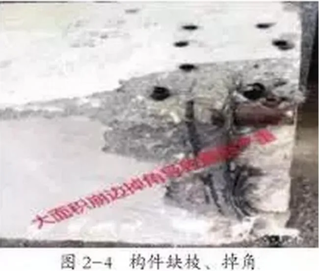
2.3 Missing Edges and Corners
Problem Description
Component edges and corners are damaged, affecting dimensional accuracy and functionality (see Figure 2-4).
Cause Analysis
Poor reinforcement design with excessive protective layers at corners; low concrete strength leading to damage during pool removal, transport, or installation; vulnerable component or mold design; aggressive demolding causing impact; uneven release agent application causing adhesion and tearing; improper handling causing collisions during discharge, transport, stacking, or hoisting.
Preventive Measures
Optimize component and mold design, adding chamfers or rounded corners and anti-cracking reinforcement where necessary. Control concrete strength before demolding and during handling, ensuring a minimum of 20MPa. Protect edges during mold removal and lifting. Strengthen quality supervision with incentives and penalties.
Handling
For damaged edges/corners exceeding 20mm, clean the surface thoroughly, apply structural adhesive, and repair with cement-based non-shrink high-strength mortar, adding reinforcement or crack-resistant fibers for large repairs. Cure with moisture for at least 48 hours, then apply necessary surface finishes. Repairs exceeding specification limits require design and supervision approval. Components failing to meet standards must be scrapped.
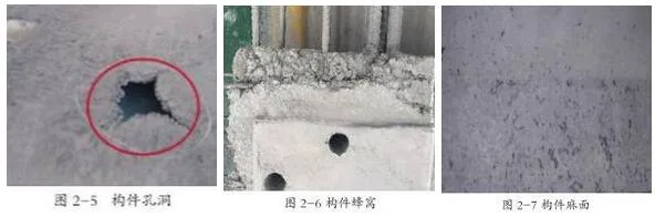
2.4 Holes, Honeycombs, and Rough Surfaces
Problem Description
Holes are deep and long voids exceeding protective layer thickness; honeycombs are areas lacking cement mortar exposing aggregate; matte surfaces have numerous small depressions without exposed reinforcement (see Figures 2-5, 2-6, and 2-7).
Cause Analysis
Insufficient vibration and compaction; uneven release agent application causing sticking; dense steel bars or embedded parts obstructing concrete flow; grout leakage at corners; poor workability causing bleeding or segregation; premature form removal; incompatible aggregate particle size.
Preventive Measures
Carefully plan steel reinforcement and embedded parts during design to facilitate pouring. Clean formwork before use and apply suitable release agents evenly. Ensure proper corner sealing. Use aggregate sizes compliant with specifications. Distribute materials properly and vibrate in layers to avoid missed areas. Address densely reinforced areas with special measures. Maintain concrete strength above 15MPa before demolding.
Handling
Clean honeycombs and rough surfaces, then repair with fine sand cement mortar, carefully curing afterward. For deeper holes, remove surface concrete and inspect internal structure. Use non-destructive or core sampling tests to ensure compressive strength. If structural integrity is intact, grout the defects and repair the surface. Components failing inspection or with extensive defects must be scrapped.
3. Common Appearance Quality Issues
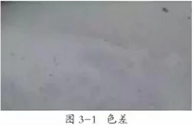
3.1 Color Differences
Problem Description
Concrete surfaces often exhibit uneven coloration, sometimes with stark contrasts due to its composite nature (see Figure 3-1).
Cause Analysis
Color variations stem from differing mix proportions, raw material changes, curing and humidity variations, concrete compaction differences, and varying release agents or form materials.
Preventive Measures
Maintain consistent raw materials and mix proportions. Clean formwork thoroughly and apply release agents evenly. Strengthen early curing for insulation and moisture retention. Control slump and vibration time for uniform compaction. Stabilize surface coating processes.
Handling
Color differences from curing typically fade naturally over time. For differences caused by mix or material changes, plain concrete may only require surface protection agents. Significant visible differences can be adjusted using color-matched pastes that do not affect later decoration.
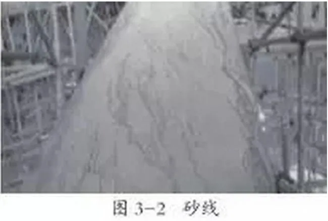
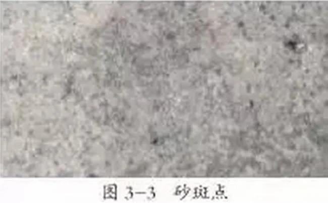
3.2 Sand Spots, Sand Lines, and Peeling
Problem Description
Fine linear or patchy sand-like marks appear on concrete surfaces, sometimes accompanied by peeling that exposes a sandy texture (see Figures 3-2 and 3-3).
Cause Analysis
Poor concrete workability and severe bleeding caused by improper aggregate gradation, low sand ratio, poor additive water retention, and excessive vibration. Surface peeling often results from inadequate secondary plastering that fails to press bleeding slurry into the structural layer. Rapid steam curing heating rates can also cause surface cracking.
Preventive Measures
Select ordinary Portland cement. Optimize admixture dosing. Adjust sand ratio and additives to improve cohesion. Use continuous grading and medium sand. Control impurities in aggregates. Determine ideal vibration methods and durations through testing. Use water-absorbing molds like wooden molds. Strengthen quality controls on secondary plastering and maintenance.
Handling
Clean defective areas and repair with fine sand cement slurry containing structural adhesive. After hardening, polish the surface evenly. Adjust mortar mix if color differences appear.
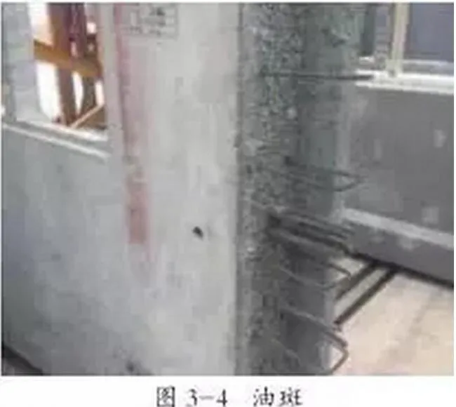
3.3 Stains
Problem Description
Due to concrete’s porous surface, it easily absorbs dirt, oil, rust, and dust, forming persistent stains (see Figure 3-4).
Cause Analysis
Incomplete mold cleaning leading to iron oxide and other residues; improper or excessive release agent application; mold contamination by floating slag; insufficient protection of finished components allowing dirt contamination.
Preventive Measures
Thoroughly clean molds before initial and repeated use. Use specialized clean demolding agents suitable for steel templates. Avoid using waste oils. Establish strict protection measures for finished products to prevent contamination.
Handling
Clean stains according to type: alkaline detergents for acidic stains, acidic detergents (e.g., oxalic acid) for rust, organic detergents for oil stains. Use gentle brushing; avoid wire brushes that can cause new discoloration.
3.4 Surface Pores
Problem Description
Concrete surfaces may have small pores (0.5–5 mm) distributed across, sometimes densely concentrated, affecting appearance (see Figure 3-5).
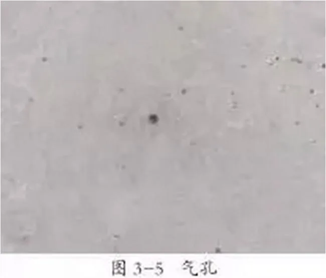
Cause Analysis
Improper mix design causing high viscosity trapping bubbles; incompatibility between cement and admixtures leading to excess air; unsuitable demolding machines causing sticky bubbles; uneven or excessive release agent application; low concrete slump limiting bubble rise; insufficient vibration time; premature demolding creating surface skin.
Preventive Measures
Choose preferred additives, release agents, and templates. Conduct mix proportion tests as needed. Determine optimal vibration procedures. Clean templates thoroughly and apply release agents uniformly. Ensure concrete strength above 15MPa before demolding.
Handling
Repair local surface bubbles with matching cement slurry. After curing, polish surfaces evenly with fine sandpaper and rinse to prevent color differences.
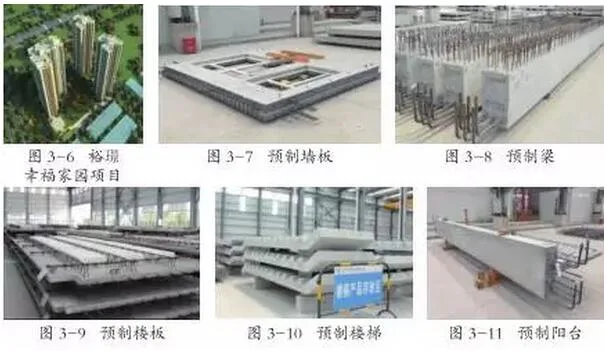
4. Case Study: Shenzhen Yujing Happy Home Project
The Shenzhen Yujing Happy Home project is the first prefabricated residential development in Shenzhen using the EPC general contracting model. It boasts the highest assembly rate in South China, exceeding 50% prefabrication. Comprising three 31-story residential buildings with podiums and two basement floors, the residential buildings use prefabricated shear wall structures, while podiums and basements use traditional cast-in-place methods.
Prefabricated construction includes interior and exterior wall panels, beams, floor slabs, stairs, and balconies (see Figures 3-7 to 3-11). The project is contracted by China State Construction Engineering Corporation Limited, with technical support from China Construction Technology Co., Ltd. Shenzhen Branch, and PC components produced by Guangdong China Construction New Building Components Co., Ltd.
Early production faced minor quality issues due to unfamiliarity among technical and management staff. These issues reflect common quality problems discussed here and can be avoided by appropriate measures. Through collaborative efforts across management, design, and production teams, PC component quality improved significantly, resulting in substantial social and economic benefits.
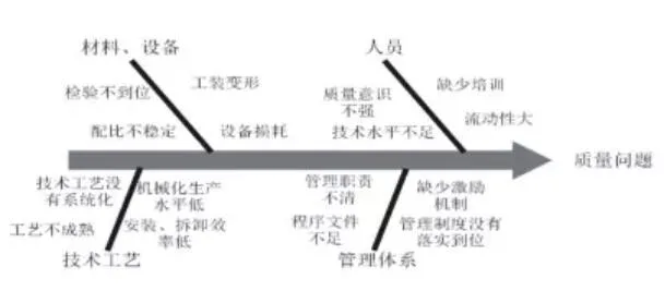
5. Conclusion
PC components are vital to the growth of prefabricated buildings, and rigorous quality management is crucial in China’s booming PC industry. This article’s analysis helps identify common quality issues, optimize control measures, and address problems effectively. Ultimately, PC quality is a comprehensive enterprise management issue requiring systematic and integrated approaches.
Below is a quality management “fishbone diagram”:
Key Focus Areas:
1. Define quality standards: Establish tailored quality standards for enterprises, projects, and products to ensure feasibility.
2. Implement a quality management system: Adopt systematic quality management approaches such as ISO standards.
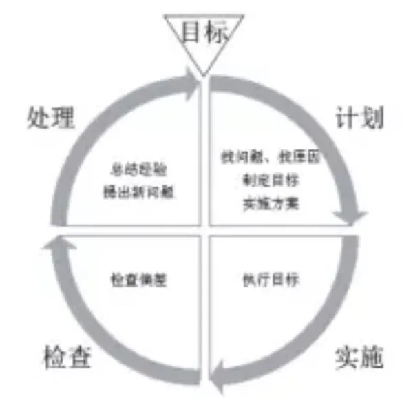
3. Continuously improve production processes: Follow the PDCA (Plan, Do, Check, Act) cycle to enhance processes and quality.
4. Ensure resource investment: Management must foster a quality-oriented culture and allocate adequate resources for quality management.
Responsible Editor: Shi Dandan


Must log in before commenting!
Sign Up