Editor’s Note: To accelerate and enhance the dissemination of industry innovations—including new policies, concepts, technologies, materials, products, projects, and experiences—and to support the sustainable development of prefabricated buildings, our platform launched a new column titled “Architecture Talk” in November last year. This column features text dialogues, audio, video, and image content, covering local discussions, expert interviews, corporate insights, and project analyses. Over 30 issues have been released so far.
We warmly invite all prefabricated building demonstration cities, industry base enterprises, members of the National Prefabricated Building Industry Technology Innovation Alliance, demonstration projects, and technology innovation bases nationwide to contribute articles or suggest interview opportunities.
Contact email: 546665581@qq.com
Contact phone: 010-66238815
In this issue, we present a case analysis of the “Jianshan Impression” prefabricated building project — focusing on the structural design section.
Following the detailed architectural design overview in the previous issue of “Zhushuo Project Analysis”, this edition introduces the project’s structural design aspects. The following content is excerpted from the book “Case Study of Prefabricated Building Engineering”:
3.2 Structural Design
3.2.1 Design Standards and Supporting Design Atlas
The structural design is based on the following standards:
- Unified Standard for Reliability Design of Building Structures GB50068-2001
- Code for Load of Building Structures GB50009-2012
- Code for Seismic Design of Buildings GB50011-2010 (2016 edition)
- Code for Design of Masonry Structures GB50003-2011
- Technical Code for Building Pile Foundations JGJ94-2008
- Technical Specification for Prefabricated Concrete Structures JGJ1-2014
- Technical Standard for Prefabricated Concrete Buildings JB/T51231-2016
- Regulations on the Depth of Compilation of Architectural Engineering Design Documents, 2008 Edition
- Technical Specification for Concrete Structures of Tall Buildings JGJ3-2010
- Classification Standard for Seismic Design of Buildings GB50223-2008
- Code for Design of Concrete Structures GB50010-2010 (2015 edition)
- Code for Design of Building Foundation GB50007-2011
- Technical Code for Waterproofing of Underground Engineering GB50108-2008
Supporting Atlas for Structural Design includes:
- Construction of Connection Nodes for Prefabricated Concrete Structures (Floor Structures and Stairs) 15G310-1
- Construction of Connection Nodes for Prefabricated Concrete Structures (Shear Wall Structures) 15G310-2
- Prefabricated Concrete Shear Wall Exterior Wall Panels 15G365-1
- Prefabricated Concrete Shear Wall Interior Wall Panel 15G365-2
- Reinforced Concrete Composite Panel for Truss (60mm Thick Bottom Plate) 15G366-1
- Prefabricated Reinforced Concrete Plate Stairs 15G367-1
- Prefabricated Reinforced Concrete Balcony Panels, Air Conditioning Panels, and Child Walls (Shear Wall Structure) 15G368-1
- Drawing Rules and Structural Sample Drawings for Concrete Structure Construction Drawing Plane Integral Representation Method 16G101-1
3.2.2 Selection of Structural System
The project uses an assembled integral cast-in-place shear wall structure combining cast-in-place shear walls with stacked horizontal components, prefabricated exterior wall hanging panels, and prefabricated interior partition walls. This system avoids vertical splicing of the main structural body and addresses common issues found in cast-in-place structures, such as short external insulation lifespan and severe external wall leakage.
It achieves integration of external wall structural insulation and decoration, enabling masonry-free construction. When combined with aluminum formworks, subsequent plastering work can be eliminated. The prefabricated exterior wall cladding undergoes multiple quality-controlled processes in the factory—tiling, finishing, insulation—improving construction quality and safety while reducing difficulties associated with high-rise facade construction.
Vertical components are all cast-in-place, with application scope and maximum height limits consistent with cast-in-place structures.
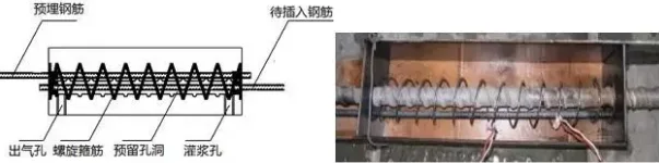
Using sleeve grouting connection technology requires precise positioning of sleeves and vertical connecting steel bars. Before concrete pouring, all sleeve openings must be sealed to prevent concrete intrusion, ensuring secure grouting and steel bar connection.
While this technology ensures reliability, it demands high precision in component production and complex construction processes. The dense vertical steel bars inside shear walls also increase costs and construction challenges.
Considering economic and technical factors alongside production and construction convenience, the prefabricated integral cast-in-place shear wall structural system was chosen for this project.
3.2.3 Structural Design Description
Project Overview:
The Jianshan Impression Public Rental Housing Project features 33 floors. The first floor has a ceiling height of 4.8 meters, with standard floors at 2.9 meters each. The total building height is 97.55 meters, employing an integral cast-in-place shear wall structure.
Design Information:
- Main structure design service life: 50 years
- Building safety use level: Level 2
- Seismic intensity at location: 6 degrees (based on China’s Seismic Parameter Zoning Map)
- Design earthquake group: First group
- Design basic seismic acceleration: 0.05g
- Site category: Class II
Classification Levels:
- Building structure safety level: Level 2
- Foundation design grade: Class A
- Seismic fortification category: Class C
- Shear wall seismic grade: Grade III
- Fire protection classification and fire resistance rating: Level 1
Structural Materials:
- Concrete strength grades: Wall columns C55~C35; beams and slabs C35
- Reinforcement: HRB400, HRB400E seismic reinforcement (Level I, II, III for framework and slant supports including stairs)
- When longitudinal load-bearing reinforcement is standard, the tensile strength/yield strength ratio ≥ 1.25, yield strength/standard value ≤ 1.30, and total elongation under maximum tension ≥ 9%
Structural Components:
- Vertical load-bearing components: fully cast-in-place shear walls
- Horizontal load-bearing components: composite beams and slabs
- Prefabricated components: composite beams, composite panels, balconies, and stairs
Non-Structural Components:
Prefabricated exterior wall cladding, partition walls, air conditioning panels, and parapets.
Interior Decoration:
Interior partitions utilize light steel keel gypsum board.
3.2.4 Design Description of Prefabricated Components
1. Composite Beam
- The joint surface between the precast beam and the subsequently poured concrete composite layer should be rough. The beam end must have a keyway, preferably rough. The keyway depth must be at least 30mm, width between three and ten times the depth. It may pass through the section; if not, the groove must be at least 50mm from the edge. The spacing between keyways equals the keyway width, with an inclination angle of no more than 30°.
Joint surfaces of cast-in-place shear walls, columns, and composite beams require strict construction joint treatment: remove debris and cement slurry, create a rough surface with at least 6mm roughness, fully moisten for no less than 24 hours, and apply bonding agent or high-grade cement mortar before construction. - Composite beam design and construction must meet BIM engineer requirements for ordinary reinforced concrete beams.
- Holes or embedded parts on beams, due to equipment needs, must strictly follow design drawings. If unspecified, additional reinforcement should be added as shown in the figure below. Reserved holes and embedded parts must be carefully reviewed before concrete pouring.
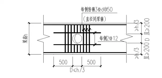
Figure 3.2.4-1 Reinforcement Bars for Beam Openings
- Composite beam reinforcement must follow these rules:
- Beam end hoop zones for seismic levels one or two must use integral enclosed hoops;
- When combining closed hoops, the open hoop reinforcement requires a 135° hook above it;
- For non-seismic design, the hook’s straight section length must be at least 5d (d = hoop reinforcement diameter); for seismic design, at least 10d;
- Open hoop ends must be closed with hoop caps on site, also with 135° hooks, following the same length requirements.
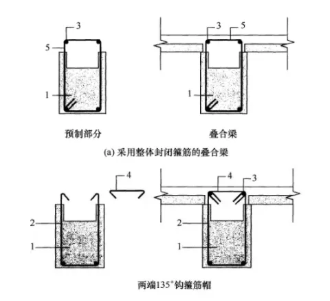
Figure 3.2.4-2 Reinforcement Structure Schematic for Composite Beams
1. Prefabricated beams; 2. Open hoop reinforcement; 3. Upper longitudinal steel bars; 4. Hoop cap; 5. Closed hoop reinforcement
5. At composite beam intersections, to facilitate lifting and construction, maintain a height difference of at least 50mm between X and Y directions at the same beam-column node.
2. Laminated Board
- The cast-in-place layer thickness is 70mm; the prefabricated layer is 60mm, totaling 130mm unless specified otherwise.
- Bottom reinforcement of the prefabricated board extends 100mm and not less than 5d in the reinforcement direction, extending beyond the support centerline.
- Reliable supports must be placed under composite panels before pouring concrete to prevent deformation under weight and construction loads, ensuring proper internal forces.
- Joint surfaces between prefabricated and cast-in-place layers require thorough treatment: debris and slurry removal, roughness of at least 4mm, full moistening for 24+ hours, and application of bonding agents or high-grade mortar before construction.
- Disassembly of laminated floor slabs must consider production mold constraints, typically limiting the short side to less than 3.2m.
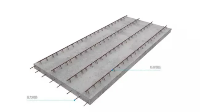
Figure 3.2.4-3 Schematic Diagram of Prefabricated Floor Slab
3. Stacked Balcony
- The cast-in-place layer thickness is 70mm; the prefabricated layer is 60mm, totaling 130mm, with the balcony slab sunk by 30mm.
- Other structural and construction requirements match those of laminated boards.
4. Staircase Board
- Prefabricated stair slabs should be integral components (see below).
- Minimum prefabricated stair slab thickness is 120mm.
- Simple support connections are recommended between stairs and supporting components: one end with a fixed hinge, the other with a sliding hinge. These must accommodate rotational and sliding deformation per interstory displacement requirements. The minimum resting length on supports must meet JGJ1-2014 Table 6.5.8.
- Sliding hinge ends require structural anti-slip measures.
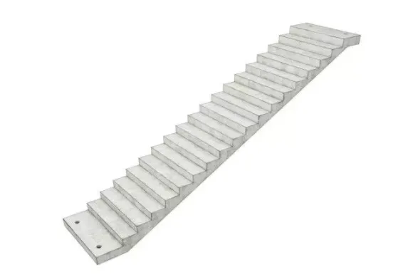
Figure 3.2.4-4 Prefabricated Staircase Schematic
5. Prefabricated Exterior Wall Cladding
- Peripheral protection uses prefabricated concrete exterior wall cladding. Connection nodes between cladding and main structure must have sufficient bearing capacity and deformation adaptability.
- Structural analysis, bearing capacity, and construction requirements comply with national standards: GB50010-2010 (2015 edition), JGJ1-2014, and JB/T51231-2016.
- During seismic design, connection nodes must allow deformation capacity at least three times the elastic interstory displacement angle of the main structure under seismic fortification.
- Concrete protective layer thickness for outermost steel reinforcement must meet:
- ≥15mm for stone or brick finishes
- ≥20mm for plain concrete
- ≥20mm from the most concave concrete surface for exposed aggregate finishes
- Joint structure requirements between wall panels:
- Must ensure waterproofing, fireproofing, and sound insulation
- Joint width must accommodate interstory displacement, sealing material deformation, construction errors, and temperature-induced deformation, with a minimum width of 15mm
- The inner and outer leaves of the exterior wall panels are connected by fiberglass reinforcement, which can be adjusted if interfering with embedded parts.
- Joint surfaces between exterior wall panels and beams should be rough with keyways. Panels anchor into structural beams and walls via reserved steel bars or bolts on sides and tops, connecting to the main structure. The exterior wall hanging panel is not part of the main structural system.
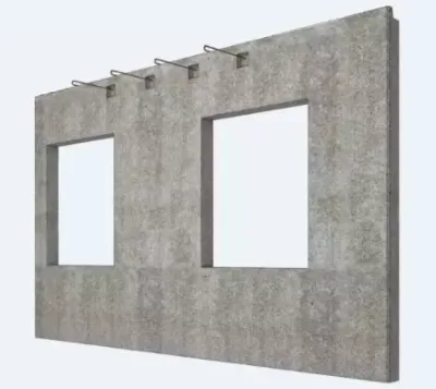
Figure 3.2.4-5 External Cladding Schematic
6. Prefabricated Interior Partition Wall
- Prefabricated lightweight partition walls used as infills must integrate with beam bottom steel bars (A6@200) by tying them together, potentially factory-integrated with composite beams.
- Design and manufacture of prefabricated lightweight infill walls must minimize self-weight while meeting fire resistance, structural load, and onsite hoisting requirements.
3.2.5 Node Design
1. Connection Between Composite Beams and Composite Slabs
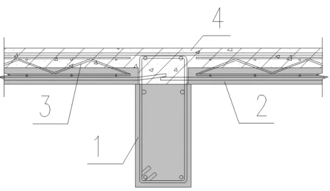
Figure 3.2.5-1 Connection Method of Prefabricated Composite Beam and Plate (Reinforcement Direction)
1. Prefabricated composite beams; 2. Prefabricated composite floor slabs; 3. Truss; 4. Cast-in-place floor slab
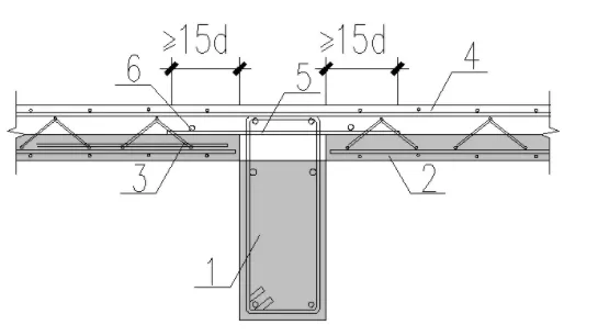
Figure 3.2.5-2 Connection Method for Prefabricated Composite Beam and Plate (Non-Reinforcement Direction)
1. Prefabricated composite beams; 2. Prefabricated composite floor slabs; 3. Truss; 4. Cast-in-place floor slab; 5. Splicing steel bars (spacing ≤ 250); 6. Additional full-length structural steel bars
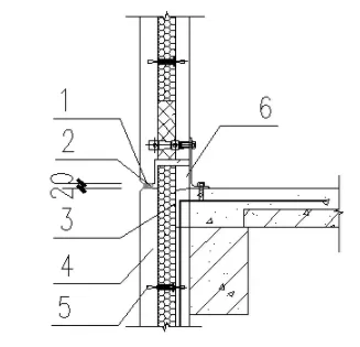
2. Vertical Connection of Exterior Cladding
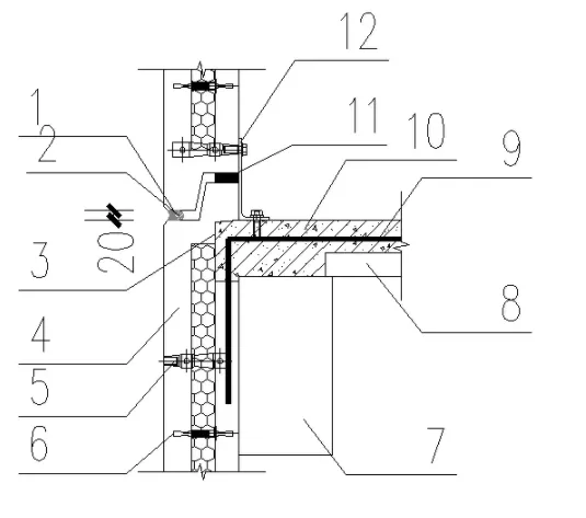
1. Building sealant; 2. Foamed polyethylene rod; 3. Wall panel slot 130×130×50; 4. Sandwich cladding; 5. External climbing frame sleeve; 6. Glass fiber reinforcement; 7. Prefabricated composite beam layer; 8. Prefabricated laminated floor slab layer; 9. Connecting steel bars; 10. Cast-in-place concrete layer; 11. Enterprise mouth; 12. Limit connector
Figure 3.2.5-3 Upper and Lower Connection Nodes of Exterior Wall Hanging Panels
Note: In Figure 3.2.5-3, the upper and lower concrete edges of the exterior cladding are sealed to reinforce the tongue-and-groove connection. The horizontal joint of the exterior wall panel uses tongue and groove primarily for waterproofing and to prevent concrete overflow during cast-in-place floor slab construction. Care must be taken not to damage the horizontal “enterprise mouth” during construction.
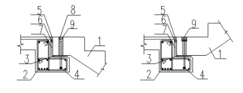
1. Building sealant; 2. Foamed polyethylene rod; 3. Wall panel slot 130×130×50; 4. Sandwich cladding; 5. Glass fiber reinforcement; 6. Enterprise mouth
Figure 3.2.5-4 Upper and Lower Connection Node 2 of External Wall Hanging Panel
Note: Figure 3.2.5-4 uses a fully broken bridge method, ideal for high energy-saving areas. The horizontal joint employs tongue and groove for waterproofing and to prevent concrete overflow during floor slab construction. The “enterprise mouth” must be carefully protected during construction.
In summary, horizontal joints of exterior wall cladding should use high-low or tongue-and-groove joints combined with waterproof materials to ensure watertightness. The tongue and groove’s form and size can be customized to simplify production and ease construction.
3. Connection of Suspended Stairs
1. Rest platform; 2. Prefabricated staircase; 3. Cement mortar leveling layer; 4. Anchor head; 5. Injection glue; 6. PE rod; 7. Polystyrene filling; 8. Grouting material; 9. Mortar sealing
Figure 3.2.5-5 Suspended Staircase
3.2.6 Project Characteristics
- The project tower employs an assembled integral cast-in-place shear wall structure, with shear wall seismic grade level three. Structural embedded parts include the basement ceiling.
- The base reinforced area uses cast-in-place concrete, above which the assembled integral cast-in-place shear wall system is applied, with external wall panels serving as enclosure and formwork for the shear wall.
- Considering economic factors, secondary beams are excluded from the structural layout.
- The bathroom uses prefabricated sunken boxes with a 400mm recess; fully prefabricated air conditioning panels are installed; balconies use stacked balcony design.
3.2.7 Summary
- Applicable Regions and Heights:
The assembled integral cast-in-place shear wall structural system—combining cast-in-place load-bearing components (shear walls, frame columns) and horizontal elements (floor slabs, frame beams)—is broadly applicable. Maximum building height depends on structure type, seismic intensity, and fortification classification. It complies with GB50011-2010 (2016 edition), JGJ3-2010, JGJ1-2014, GB/T51231-2016, and local regulations. For frame, tube, or complex high-rise structures exceeding 50 meters, measures like thickening composite floor slabs are recommended to enhance stiffness by increasing cast-in-place layer thickness and reinforcement. - Technical Considerations:
- The external wall hanging panel acts as the enclosure, requiring reserved steel bars and keyways at the top edge of wall panels to connect reliably with main beams or slabs via concrete pouring.
- The system must ensure the safety of external cladding and its connection without compromising the main structure’s stiffness or internal force distribution.
- Waterproofing, fireproofing, soundproofing, and thermal insulation must be applied to gaps between exterior cladding and the main structure, avoiding rigid fillers.
- Besides secure connection, exterior cladding requires positioning and limiting devices outside the plane.
Due to copyright restrictions, this edition provides only the architectural and structural design, equipment design, PC detailing, and construction management aspects of the project. The content is selected from “Prefabricated and Prefabricated Construction Engineering Cases”, part of the “Prefabricated and Prefabricated Construction Technology Series”. For more detailed project information, readers can scan the QR code below to purchase the book.
This series reviews 20 years of research achievements by Changsha Yuanda Residential Industry Group, summarizing applicable experiences for prefabricated building construction in China today. It covers design and construction planning, main construction, waterproofing, and overall bathroom installation.

The series includes seven volumes: “Collection of Key Points for Prefabricated Construction”, “200 Cases of Prefabricated Construction Problems and Prevention”, “Prefabricated Villa Atlas”, “Technical Guide for Prefabricated Concrete Pipe Gallery”, “Key Points for Quality Control of Prefabricated Construction Supervision”, “Valuation of Prefabricated Concrete Structure Engineering Quantity List”, and “Prefabricated Construction Engineering Cases”.


Must log in before commenting!
Sign Up