Preface
Fair-faced concrete refers to concrete that directly utilizes the natural texture of the formed surface as a decorative feature. Although plain concrete first appeared in China during the 1970s, it did not gain widespread development until the late 1990s. Today, architects increasingly favor clear water concrete for its unique skin texture and the artistic effect of presenting a smooth, elegant surface that reveals the inherent beauty of the material.
Prefabricated concrete components are concrete elements cast and molded in factories or on-site using molds, cured to the required strength, and then installed at the project location. These prefabricated plain concrete components demand strict control over external dimensions, visible quality, color uniformity, and overall decorative appearance.
Compared to traditional cast-in-place construction, prefabricated buildings offer advantages such as improved quality and safety, enhanced efficiency, shortened construction periods, better working conditions, labor savings, and promotion of energy conservation and emission reduction. In recent years, China has strongly promoted prefabricated buildings, with precast concrete components playing a critical role. The technology and quality control of these components are vital for companies specializing in prefabrication.
Beijing Yugou Co., Ltd. has recently completed several notable precast concrete projects, including the China Building Technology Center cladding, Soft Power Building cladding, floor tiles for the Beijing Palace Museum, exterior wall cladding for the Beijing Tongzhou City Sub-center office building, and the Tianjin Vanke Gemini sculpture.
1. Typical Types and Forming Methods of Prefabricated Components
Different component types require different molding methods. To maintain the appearance of plain concrete, the exposed surfaces of prefabricated components must contact the formwork closely to minimize manual finishing.
1.1 Plate-type Components
For plate components such as prefabricated wall panels and viewing platforms with large surface areas, a one-time reverse molding process is preferred to ensure the quality of the exposed surface. The reverse printing process involves casting the concrete with the exposed surface against the mold, resulting in a finished face that reflects the mold’s texture and pattern.
When the production direction aligns with the intended use direction, it is termed the positive printing process; otherwise, it is called the reverse printing process. Reverse casting is widely used for precast concrete components, where patterned lining molds are placed on the base mold so that the visible surface faces downward during casting. This technique immediately imparts various textures and patterns onto the exterior wall panels during pouring.
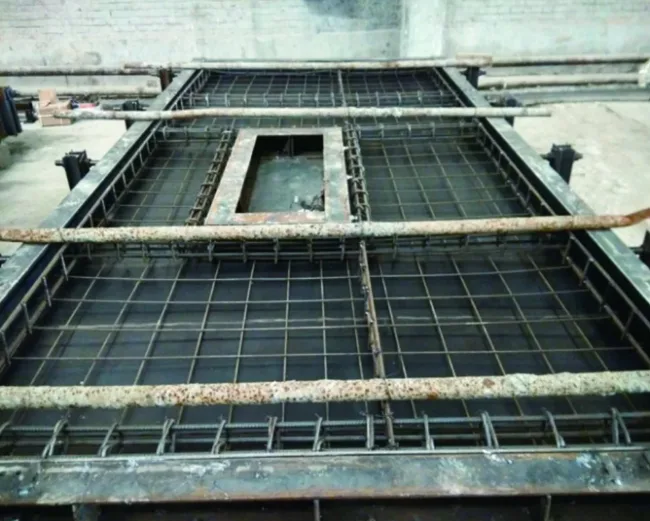
Figure 1: External wall hanging panel reverse template
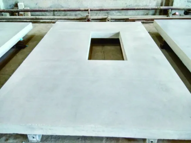
Figure 2: Finished external wall hanging board
1.2 Stairs
Two common methods are used for prefabricated stairs: reverse molding and side standing production. When both the steps and the back require a clear water finish, side standing production is preferred. Known as the standing mold process, this method uses a vertically positioned mold. Compared to flat mold casting, it saves production space and improves efficiency. Both surfaces of the component are smooth, reducing manual finishing and ensuring the clear water effect on the visible side. The wall-facing or handrail side is typically a manually finished surface.
Side standing production is commonly applied to simple-shaped components requiring flatness on both sides, such as prefabricated staircases.
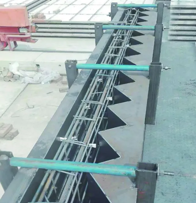
Figure 3: Prefabricated staircase mold
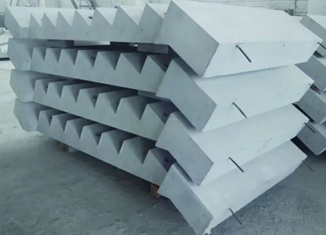
Figure 4: Prefabricated staircase finished product
1.3 Beams
Prefabricated beams typically have large exposed surfaces, with the top surface requiring reinforcement and roughening. For beams with high side exposure and appearance requirements, a straight cut forming method is used.
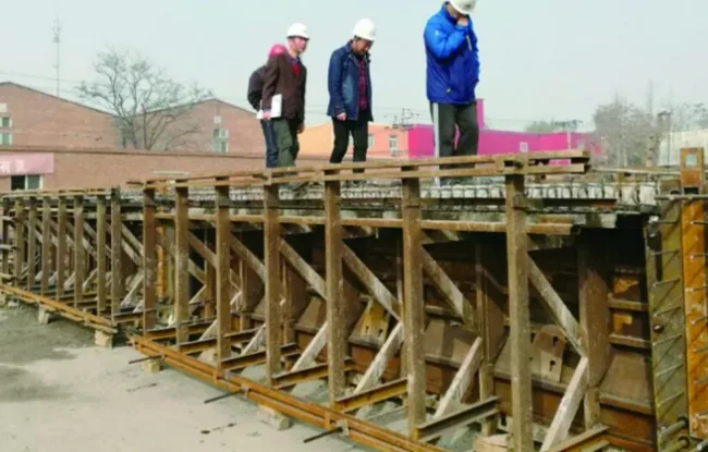
Figure 5: Prefabricated beam mold

Figure 6: Prefabricated beam finished product
1.4 Columns
Due to their height, prefabricated columns are preferably produced using the side standing method, which reduces worker risk while ensuring component quality. Two columns can share a side mold to cut costs.
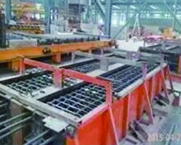
Figure 7: Prefabricated column mold
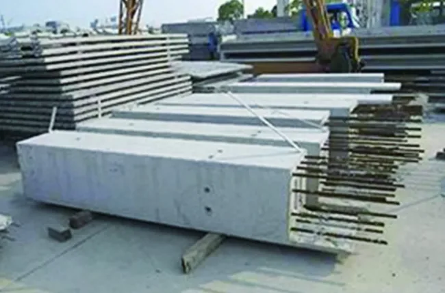
Figure 8: Prefabricated column finished product
2. Molds
The mold is the core and foundation for producing prefabricated plain concrete components. Steel molds are typically used, and choices regarding steel plate quality, mold design, detail treatment, and welding significantly affect mold and component quality.
2.1 Steel Plate Material Selection
Molds must have sufficient strength, stiffness, and stability to withstand the weight, lateral pressure, and work loads during casting. Generally, Q235 steel plates with dense, uniform oxide layers and smooth surfaces free of defects (distortion, folds, cracks, rust, scratches) are used. Low-quality steel can release oxides during steam curing, contaminating the component surface. Wuhan Iron and Steel (Group) Corporation produces steel plates of suitable quality for plain concrete molds.
2.2 Mold Technology Approaches
Mold technical solutions vary depending on component characteristics, with different production processes adopted accordingly. Reverse casting and side casting are common for achieving the decorative effect of plain water concrete.
2.2.1 Reverse Casting Process
This process uses the clear water surface as the exterior finish, casting the concrete so its outer surface contacts the mold base plate. The steel plate’s surface quality ensures smoothness, gloss, linearity, and precise angles on the finished face.
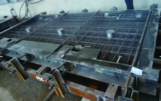
Figure 9: Reverse printing process mold
2.2.2 Side Casting Process
When two or three main exposed surfaces require a clear water finish, side casting is recommended. The component is rotated 90 degrees from its normal use orientation during production.
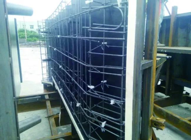
Figure 10: Side molding process mold
In side standing production, all surfaces except the top contact the mold, greatly enhancing appearance quality. Manual finishing is limited to the top surface, reducing human error that could lead to defects.
2.3 Key Points in Mold Production
2.3.1 Steel Plate Cutting
High dimensional accuracy is essential for molds of plain concrete components. Laser cutting is recommended to achieve precise dimensions and smooth edges free of burrs. Decisions on whether to cut molds in one piece or splice them depend on component characteristics. Mold design, cutting, and assembly should allow for modifications if needed.
2.3.2 Ensuring Dimensional Accuracy
The mold base must be sturdy. Fixing methods should be tailored to component size, with side supports added for large elements to prevent bending and maintain straightness. Horizontal tooling ensures vertical flatness, and diagonal braces stabilize large, heavy components, keeping overall dimensions within tolerances.
2.3.3 Corner Treatment
Since the aesthetic appeal of precast components often depends on their cross-sectional lines and angles, production plans must ensure straight, smooth edges and precise, consistent angles. Straight edges are usually spliced tightly, while curved edges and corners are formed in one piece with bending. Chamfering is commonly applied to outer surfaces to enhance aesthetics and facilitate demolding.
2.3.4 Preventing Grout Leakage at Joints
When molds are spliced, sealing joints to prevent grout leakage is critical. Weld seams should be fully welded, polished, and free of pores or slag inclusions.
(1) Welding: Compared to traditional manual arc welding, carbon dioxide shielded welding offers benefits such as faster speed, no need to change rods, lower cost, and improved quality and efficiency. Manual arc welding remains useful for small welds and repairs.
(2) Edge and Corner Sealing: Side molds on bottom molds should be welded or firmly pressed and sealed with sealant. Side molds adjacent to bottom molds must be fixed with push screws or positioning pins for a tight fit. Foam sealing strips should be applied at joints and trimmed to prevent mortar leaks and maintain straight seams. Chamfers also require sealing to avoid leakage. Bending steel plates requires precise preparation and use of appropriate dies to achieve smooth, accurate bends.
3. Raw Materials and Concrete Properties
Clear-faced concrete components must meet mechanical and durability requirements and deliver the unique “clear water” decorative effect. The choice of raw materials and mix design is critical.
3.1 Selection of Raw Materials
Raw materials include cement, admixtures, sand, aggregate, and additives. Selecting manufacturers with stable production capacity helps ensure consistent color and performance. Materials should come from the same source and batch to avoid color variations. Admixtures should not alter concrete color.
3.2 Performance Requirements
Low-alkali cement is preferred, meeting standards for color, consistency, setting time, surface area, stability, and strength, with minimal variability. Class F Grade I or II fly ash is recommended; finely ground secondary fly ash is discouraged due to impurities that degrade appearance. Loss on ignition in fly ash should be controlled to ≤ 5%.
Mineral powder use should be limited, as hydration can cause green discoloration and sensitivity to curing temperature. S95 grade mineral powder varies greatly in color and quality; strict batch testing is essential.
Sand and aggregate must meet standards for color, mud content, and grading, with low variability to maintain concrete stability and appearance.
Polycarboxylate-based water reducers are commonly used additives. They must not affect concrete color or cause surface bubbles. Each batch requires testing for color, water reduction, slump retention, and air content.
3.3 Material Performance Testing
Beyond national standards, enhanced on-site testing is necessary. Each delivery must be sampled for color consistency in different parts of the vehicle, inspected upon arrival, and tested more frequently if needed.
3.4 Mix Design and Testing
Mix design follows GB 50204-2015 and JGJ 55-2011 standards. To ensure consistent color in plain concrete, a single fly ash approach is generally used.
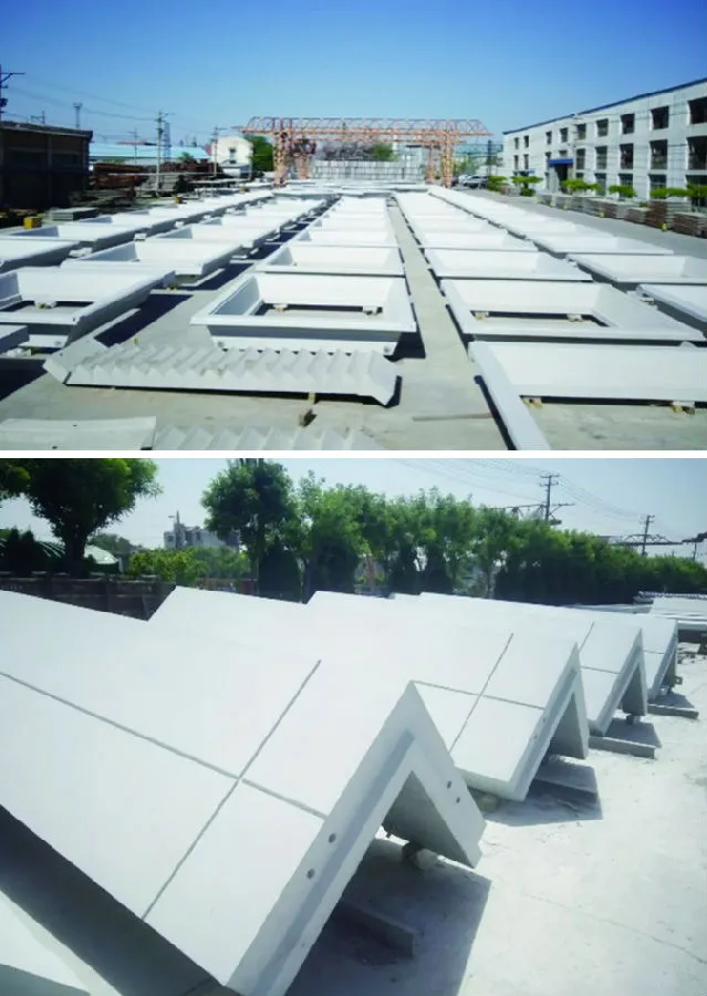
Figure 11: Effect of plain concrete
Workability during pouring significantly affects the finished surface. Tests such as slump, slump loss over time, and air content ensure slump loss stays within 20 mm during pouring. Mechanical performance is verified on test blocks, with additional tests for impermeability and durability as required.
4. Pouring and Vibration Process
4.1 Selection and Application of Release Agent
Choosing the right release agent is critical for appearance. It must facilitate easy demolding, quick drying, easy cleaning, be harmless to concrete, and resist water and weather. Additionally, it should:
- Leave fewer bubbles and produce a glossy surface after demolding;
- Not affect the decorative concrete surface or cause discoloration;
- Not corrode steel molds, reinforcement, or concrete.
Application guidelines (shown in Figures 12 and 13) include:
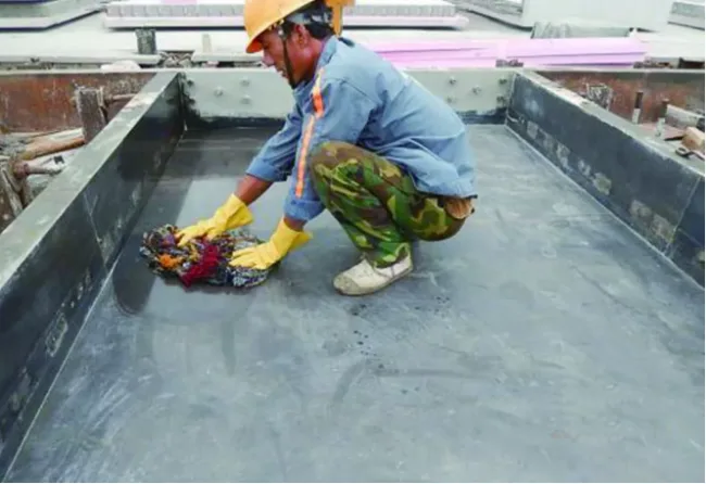
Figure 12: Applying release agent with cotton thread
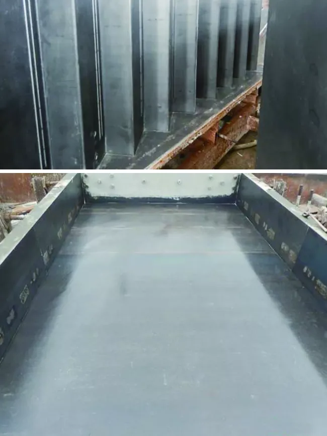
Figure 13: Effect after applying release agent
- Ensure the mold is free from water, ice, snow, ash, or debris before application, and apply evenly without pooling or buildup.
- Avoid dripping release agent on reinforcement or embedded parts to maintain proper bonding.
- Reapply release agent if washed away by rain.
- Stir the agent well before use; never add water.
4.2 Pouring and Forming
Pouring methods and sequences greatly influence component quality. Proper planning of pouring sequence, height, and points is essential to avoid color inconsistencies and defects.
- Clean the mold thoroughly before pouring; remove dust with a vacuum or blower.
- Use vibration tables for flat components and vibrating rods for higher parts. Vertically cast components require attached vibrators and inserted vibrating rods.
- Ribbed flat plate components are poured in two stages: surface first, then ribs after placing suspended formwork. Measure thickness after compaction and add or remove material as needed without stirring compacted concrete.
- For L- or U-shaped plates with high beams, pour horizontal parts first, then cover and pour beams, preventing concrete flow from beams to horizontal parts during vibration.
- After pouring, smooth and press the surface once, then level plastering with a straightedge. Use an iron trowel to polish twice, avoiding plastering marks.
4.3 Vibration Methods Impact
Choose vibration methods suited to component characteristics. Common methods include desktop vibration, attached vibration, and inserted vibrating rods. Proper vibration reduces bubbles, improves density, and enhances surface quality.
Desktop and attached vibrations offer more uniform effects, while inserted rods provide flexibility. Key points during vibration:
- Avoid vibrating reinforcement, molds, or plates with inserted rods.
- Control vibration duration to prevent defects like bubbles, sand lines, or color variations.
- Ensure uniform vibration distribution throughout the component.
- Use vibrating rods horizontally on thin plate surfaces.
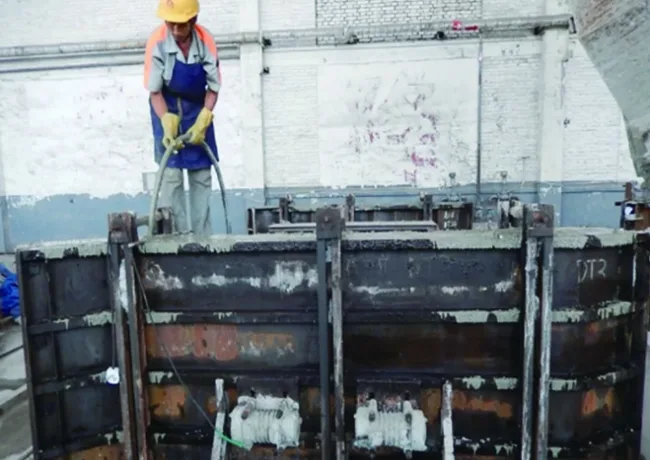
Figure 14: Combined use of attached vibrator and vibrating rod
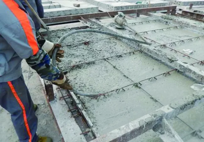
Figure 15: Horizontal use of vibrating rod
5. Steam Curing and Surface Protection
5.1 Steam Curing Temperature Control
Prefabricated plain concrete components should be steam cured using an automatic temperature control system (Figure 16). The curing temperature influences surface color: higher temperatures and early demolding yield lighter, whiter surfaces, while lower temperatures result in darker gray tones. Therefore, temperature ramp-up, ramp-down rates, and maximum holding temperatures must be strictly controlled.
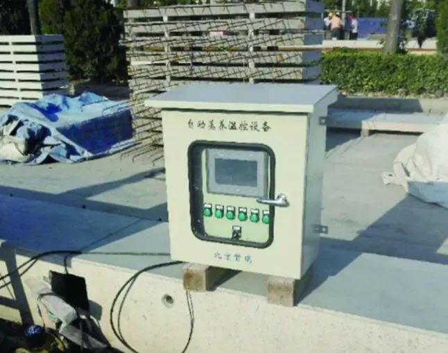
Figure 16: Automatic steam curing temperature control equipment
Consistent curing plans should be developed for all precast components within a project to ensure uniform color. Automated systems reduce human error, maintaining consistent curing conditions and minimizing color variations and defects.
5.2 Steam Pipe Arrangement
Steam pipes should be strategically placed based on component size to maintain surface quality. Typically, pipes are positioned at each end of the formwork and, for components longer than 10 meters, an additional pipe is placed mid-length. To prevent direct steam impact, outlets are angled at 30 degrees to promote even steam circulation.
5.3 Surface Protection
Surface protection technologies enhance permeability, breathability, waterproofing, and environmental friendliness without altering the base color or appearance. They protect concrete from water-borne erosion, mold, moss, weathering, salinization, alkali reactions, pollution, and maintain cleanliness, thereby extending service life.
Silane-based protective agents, relying on impregnation principles, are the most commonly used and effective for plain concrete.
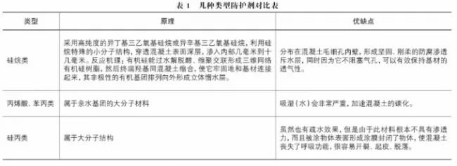
Table 1: Comparison of various protective agents
Figures 17 and 18 illustrate the effects of protective agent application by Beijing Yugou Co., Ltd. In Figure 17, the left panel was treated with a water-based agent and the right with an oil-based agent; both provide effective protection. Figure 18 shows an uncoated side of a hanging board with visible cracking, highlighting the importance of surface protection.
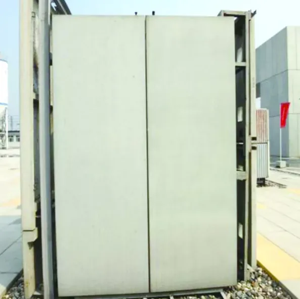
Figure 17: Effect of coated protective agent
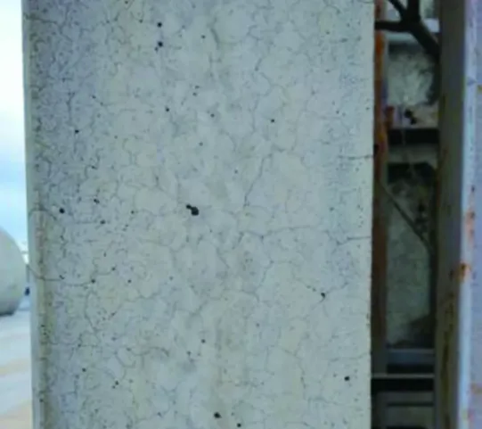
Figure 18: Effect of uncoated protective agent on the side
6. Finished Product Protection
Protecting finished precast components is vital during demolding, stacking, loading, transportation, and site installation to preserve their fair-faced concrete appearance.
6.1 Impact Protection
- After confirming embedded parts and dimensions, flip boards promptly to facilitate evaporation and ensure color uniformity, protecting corners during handling to avoid damage.
- Use hard materials like plywood and plastic to shield vulnerable external corners after demolding.
- During loading, place special corner protectors where cables contact components to prevent damage. Fix components with soft materials, avoiding direct contact with steel wire ropes.
6.2 Pollution Prevention
- Separate wooden stacking pads with white polystyrene boards or wrap them with plastic film to prevent staining from moisture.
- Keep boards free from dirt; avoid oil drips from lifting equipment and prevent workers from handling surfaces with dirty or oily gloves.
- Cover the top piece when stacking components unless otherwise specified. Store vertically on racks with protective measures where surfaces contact the rack to prevent contamination.
- For vertical transport, secure components with transport frames that include anti-pollution protection at contact points.
Analysis of Causes and Solutions for 7 Common Quality Issues
Prefabricated plain concrete components generally offer superior quality and color uniformity compared to cast-in-place concrete, effectively avoiding defects like honeycombing, rough surfaces, holes, and exposed reinforcement. However, issues like color differences, sand lines, or spots may still occur, affecting appearance.
7.1 Sand Lines or Spots
Cause: Excessive slump or bleeding leads to uneven mixture, causing water accumulation and sand lines or spots.
Control: Strictly control slump by adjusting mix proportions or additives to maintain water retention, cohesiveness, and flowability.
7.2 Color Differences
Causes: Five main factors contribute:
- Poor workability and uneven vibration causing inconsistent contact with the mold;
- Significant slump variation;
- Inconsistent raw materials;
- Variations in curing and temperature control;
- Post-demolding exposure to environmental factors.
Control Measures:
- Ensure consistent workability and controlled vibration during pouring;
- Maintain slump within ±10 mm and limit slump loss during pouring to ≤20 mm;
- Conduct thorough color inspections for each batch of raw materials;
- Implement uniform curing systems with consistent temperature and rigorous monitoring;
- Apply timely protective treatments after demolding, including covering when necessary.
Author: Liu Hao


Must log in before commenting!
Sign Up